
Image capturing apparatus and control method thereof

Active Publication Date: 2019-12-26
CANON KK
View PDF2 Cites 0 Cited by
  • Summary
  • Abstract
  • Description
  • Claims
  • Application Information

AI Technical Summary

Benefits of technology

The present invention provides an image capturing apparatus that can capture still images without interrupting the recording of a moving image without being affected by the decoding circuit configuration.

Problems solved by technology

However, the FHD size is a size that is acquired by thinning out image signals from an image sensor, and thus a resulting photograph has an image quality degraded compared to the original still image.
However, in this processing, since a process for stopping moving image shooting is interposed while a moving image is being shot, a problem occurs in which continuity of a moving image file that is recorded is partially interrupted.
Furthermore, if the above-described configuration is adopted in which image signals for a still image size and image signals for a moving image size can be output from the image sensor at the same time, a problem occurs in that the circuit scale increases since even the image capturing signal processing circuit requires two decoding circuits.
In addition, if there is only one decoding circuit in the image capturing signal processing circuit, a moving image and a still image that are output from the image sensor cannot be received at the same time, and a problem still occurs in that, if still image shooting is performed while a moving image is being recorded, the moving image is interrupted.

Method used


Image

  • Image capturing apparatus and control method thereof
  • Image capturing apparatus and control method thereof
  • Image capturing apparatus and control method thereof

Examples


first embodiment

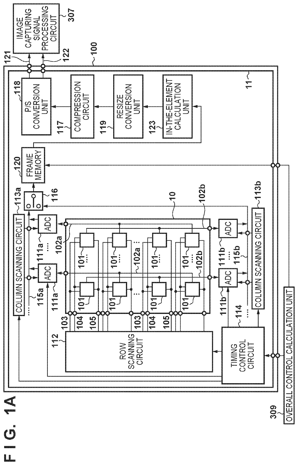
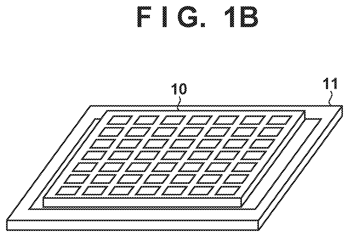
[0030]FIG. 1A is a block diagram showing the configuration of an image sensor 100 in a first embodiment of the present invention, and FIG. 1B is a schematic diagram showing the outer appearance of the image sensor 100. As shown in FIG. 1B, the image sensor 100 is formed of a first semiconductor chip 10 (image capturing layer) and a second semiconductor chip 11 (circuit layer), and the first semiconductor chip 10 is stacked on the second semiconductor chip 11.

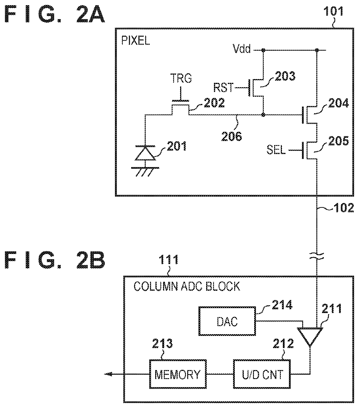
[0031]In the first semiconductor chip 10, a pixel portion consisting of a plurality of pixels 101 that are arranged in a matrix is arranged on the light incident side, in other words the light receiving side of an optical image. The pixels 101 arranged in a matrix on the first semiconductor chip 10 are connected to transfer signal lines 103, reset signal lines 104, and row select signal lines 105 in the horizontal direction (row direction) in units of rows. Meanwhile, the pixels 101 are connected to column output lines 102a or 1...

second embodiment

[0109]In the first embodiment, a configuration is adopted in which, when compressed moving image signals and still image signals are transferred from the image sensor 100 at the same time, the moving image signals and still image signals are respectively supplied to the image capturing signal processing circuit 307 and the first memory unit 308. On the other hand, in a second embodiment, control performed by an image sensor 100 when the number of decoding circuits of an image capturing signal processing circuit 307 is one will be described. Note that the configuration of an image capturing apparatus in the second embodiment is the same as the first embodiment, and thus a description thereof is omitted.

[0110]FIG. 13 is a control timing diagram of the image sensor 100 in the second embodiment. The image sensor 100 operates at 60 fps (frame / second), but moving image signals are transferred to the image capturing signal processing circuit 307 once in two frames.

[0111]On the other hand, ...

third embodiment

[0123]In this third embodiment, control that is handled by an image sensor 100 when the number of decoding circuits of an image capturing signal processing circuit 307 is one similar to the second embodiment will be described. Note that the configuration of an image capturing apparatus in the third embodiment is same as the first embodiment, and thus a description thereof is omitted.

[0124]FIG. 15 is a control timing diagram of the image sensor 100 in the third embodiment. The image sensor 100 operates at 60 fps (frame / second), and transfers signals to the image capturing signal processing circuit 307 for each frame.

[0125]On the other hand, regarding still image signals, when an instruction that is based on a user operation on an operation unit 315 is received by an overall control calculation unit 309, and if it is determined that still image shooting is to be started, the overall control calculation unit 309 permits transfer of still image signals of the image sensor 100, and at th...


PUM


Abstract

An image capturing apparatus comprises an image sensor, a readout circuit capable of performing a first readout operation of reading out a first image signal and a second readout operation of reading out a second image signal for which the number of pixels is larger than the number of pixels for the first image signal, a compression circuit that generates a first compressed image signal by compressing the first image signal, and generates a second compressed image signal by compressing the second image signal, a decoding unit configured to decode the first compressed image signal and second compressed image signal, and a control unit configured to perform control so as to transfer the second compressed image signal to the decoding unit during a period during which the decoding unit is not decoding the first compressed image signal.

Description

BACKGROUND OF THE INVENTIONField of the Invention[0001]The present invention relates to an image capturing apparatus and a control method thereof.Description of the Related Art[0002]In recent years, digital cameras capable of shooting a still image during moving image shooting have been manufactured as products. In such digital cameras, if a still image is shot while a moving image is being shot, a moving image file and a still image file are separately recorded.[0003]In most cases, an ordinary recording size of a moving image is a size called full HD (FHD), and a still image can be recorded by being extracted from the moving image if the size of the still image is the FHD size that is same as the moving image. However, the FHD size is a size that is acquired by thinning out image signals from an image sensor, and thus a resulting photograph has an image quality degraded compared to the original still image. In view of this, when shooting a still image during moving image shooting, ...

Claims


Application Information

Patent Timeline
IPC IPC(8): H04N5/232H04N5/04
CPCH04N5/23232H04N5/04H04N5/23245H04N23/951H04N23/667H04N25/42
Inventor FURUMOCHI, HIROYUKI
Owner CANON KK
Learn More