


Quick Research
Generate reliable direction feasibility study reports for your R&D in just a few steps.

Technical Q&A
Discover and master advanced knowledge NOW. Basics, ideas, possibilities, all at once.

Find Solutions
As an expert in R&D theories, this can generate solutions to your technical problems instantly.

Evaluate Feasibility
Analyze your overall solution with one click, know your potential R&D risks in advance.

Monitor Landscape
Get weekly tech updates, stay abreast of the latest tech innovations and key insights.
Dental post, method for its fabrication, and set of dental posts
a technology for dental posts and dental cavities, applied in dentistry, medical science, teeth capping, etc., can solve the problems of unsatisfactory fixation of this previously known post inside a dental cavity, unoptimally suited for a fitting inside an oval or curved cavity, and a limiting factor of the fixation strength of the dental post inside the dental cavity, so as to avoid the delamination effect of the fibers
- Summary
- Abstract
- Description
- Claims
- Application Information
AI Technical Summary
Benefits of technology
Problems solved by technology
Method used
Image

Examples
first embodiment
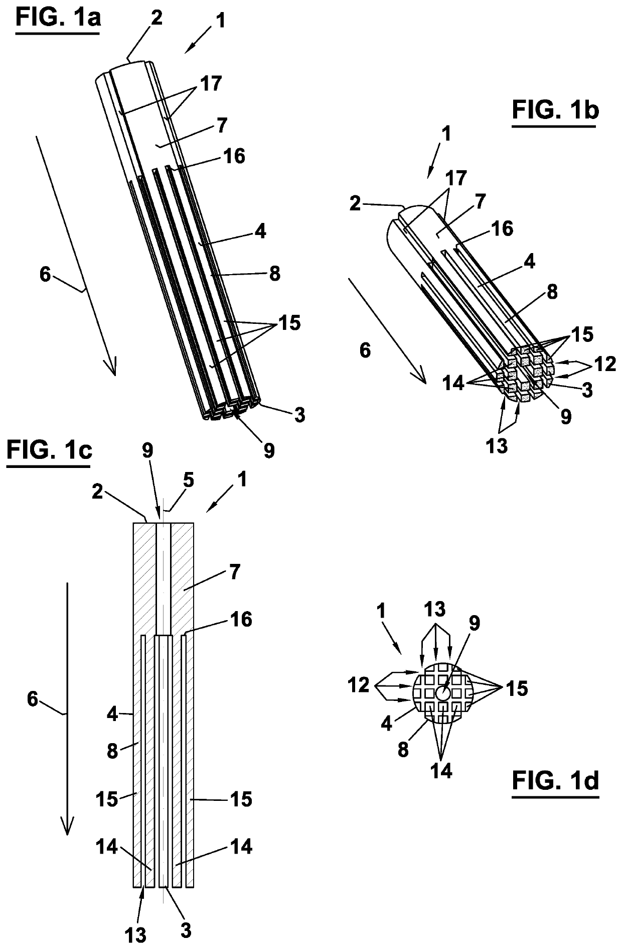
[0062]A dental post 1 as depicted in FIGS. 1(a)-(d), is formed from a solid piece of a circular cylindrical body. The body is composed of a composite material comprising a resin matrix that is reinforced with fibers. The fibers extend from a free upper end 2 to a free lower end 3 of post 1 over a total length of post 1. The fibers are uniformly directed in parallel with respect to a central axis 5 of post 1. The fibers thus extend in an axial direction 6 pointing in the direction of central axis 5 of post 1. The resin consists of a polymer derived from a methacrylate monomer, preferably methyl methacrylate (MMA) or urethane dimethacrylate (UDMA). Mineral particles, preferably ytterbium fluoride and / or ytterbium oxide, are homogenously distributed within the resin. The fibers are constituted by glass fibers, wherein the fiber content represents ideally 80% of the volume of post 1. The fibers are treated with silane as a coupling agent to the resin matrix. An enveloping surface 4 of ...
second embodiment
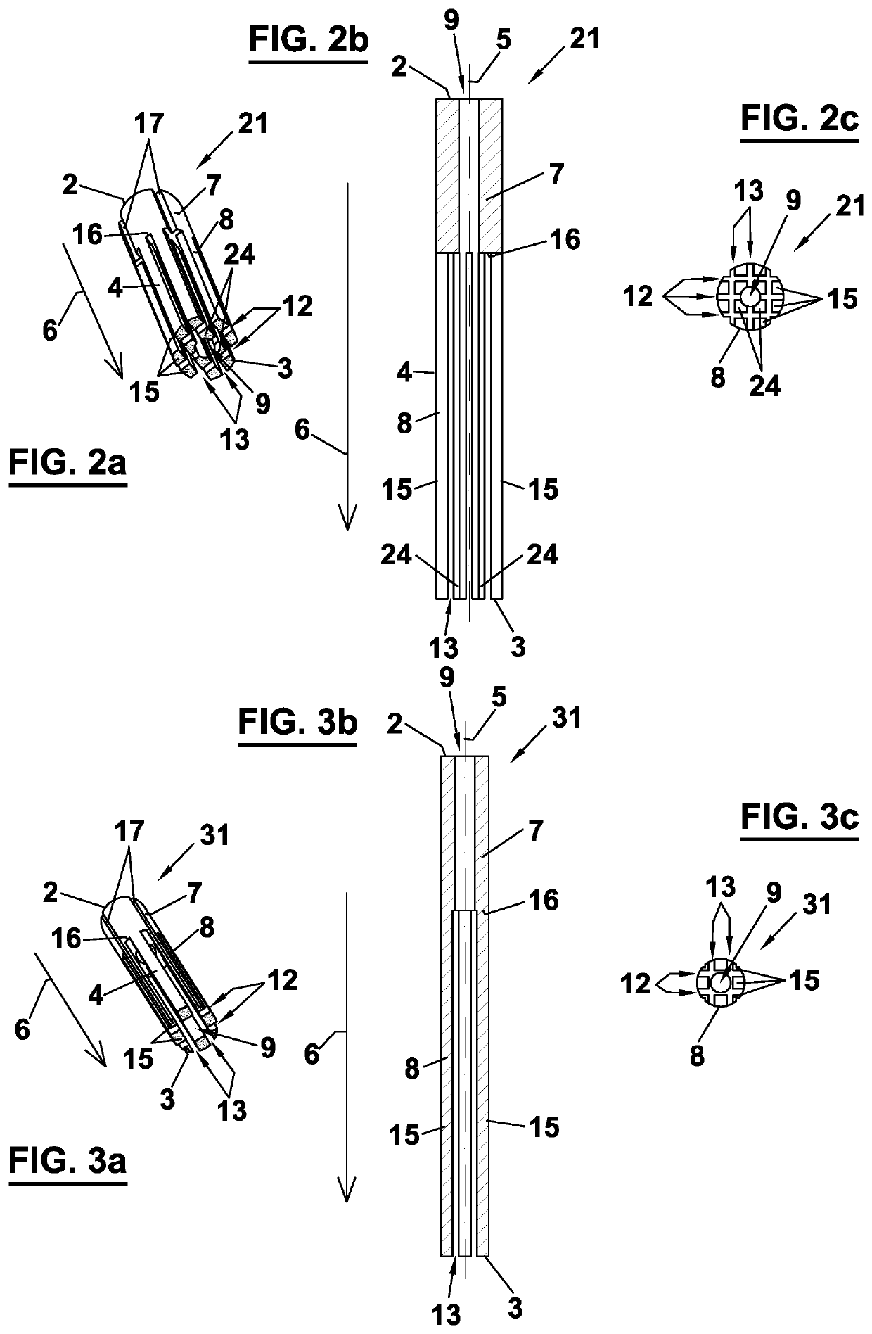
[0068]FIGS. 2(a)-(c) show a dental post 21 according to a Structural elements and constituent parts corresponding to the embodiment of dental post 1 depicted in FIGS. 1(a)-(d) are indicated by the same reference numbers. Subsequently, only the differences of dental post 21 with respect to dental post 1 are described.
[0069]Head portion 7 and foot portion 8 of post 21 have a smaller width perpendicular to central axis 5 as compared to post 1. The width of head portion 7 and foot portion 8 of post 21 is at least 0.5 mm and at most 2 mm. The slits provided by planar cut-outs 12, 13 in foot portion 8 of post 21, however, have the same width perpendicular to axial direction 6 and the same spacing from one another as compared to slits 12, 13 in foot portion 8 of post 1. Thus, as a result of the smaller width of post 21, foot portion 8 of post 21 only comprises eight radially outer rods 15 and four radially inner rods 24. Inner rods 24 of post 21 are further distinguished from inner rods 1...
third embodiment
[0070]FIGS. 3(a)-(c) show a dental post 31 according to a Structural elements and constituent parts corresponding to the embodiment of dental post 1 and 21 depicted in FIGS. 1(a)-(d) and FIGS. 2(a)-(c) are indicated by the same reference numbers. Subsequently, only the differences of dental post 31 with respect to dental post 1 and 21 are described.
[0071]Head portion 7 and foot portion 8 of post 31 have a smaller width perpendicular to central axis 5 as compared to post 1 and post 21. The width of head portion 7 and foot portion 8 of post 31 is at least 0.3 mm and at most 1 mm. The slits provided by planar cut-outs 12, 13 in foot portion 8 of post 21, however, have the same width perpendicular to axial direction 6 and the same spacing from one another as compared to slits 12, 13 in foot portion 8 of post 1 and 21. Thus, as a result of the smaller width of post 31, foot portion 8 of post 31 only comprises eight radially outer rods 15 and no radially inner rods.
[0072]At least two of ...
PUM
 Abstract
Description
Claims
Application Information
 - R&D Engineer
- R&D Manager
- IP Professional
- Industry Leading Data Capabilities
- Powerful AI technology
- Patent DNA Extraction
Browse by: Latest US Patents, China's latest patents, Technical Efficacy Thesaurus, Application Domain, Technology Topic, Popular Technical Reports.
© 2024 PatSnap. All rights reserved.Legal|Privacy policy|Modern Slavery Act Transparency Statement|Sitemap|About US| Contact US: help@patsnap.com