Test chamber and method

a test chamber and fluid technology, applied in the operation mode of machines, instruments, lighting and heating apparatus, etc., can solve the problems of consuming a comparatively large amount of energy by cascading cooling devices, affecting etc., and achieve the effect of prolonging the service life of compressors

Active Publication Date: 2019-12-19
WEISS TECH GMBH
View PDF0 Cites 4 Cited by
  • Summary
  • Abstract
  • Description
  • Claims
  • Application Information

AI Technical Summary

Benefits of technology

The invention is about a method to cool a heat exchanger using a cascading cooling system. The method allows the heat exchanger to be cooled either using only one circuit or by combining both circuits depending on the temperature requirements. This method increases the thermal efficiency of the cooling system and saves energy compared to traditional methods. The compressor can also be turned off if not needed, allowing the heat exchanger to cool for longer periods of time. The method allows for more precise regulation of the cooling system and direct cooling of circulated air in a test space.

Problems solved by technology

In this context, however, it is disadvantageous for a compressor to always have to be in operation when there is a slight difference in temperature present in the heat exchanger, no matter how large the difference in temperature to be compensated by the cooling device is.
Since continually turning the compressor on and off is not possible and a fan has to be operated at the condenser also if need be, the cascading cooling device also consumes a comparatively large amount of energy for slight differences in temperature, which are to be compensated in the heat exchanger, using the known operating method described above.

Method used


Image

  • Test chamber and method

Examples


Embodiment Construction

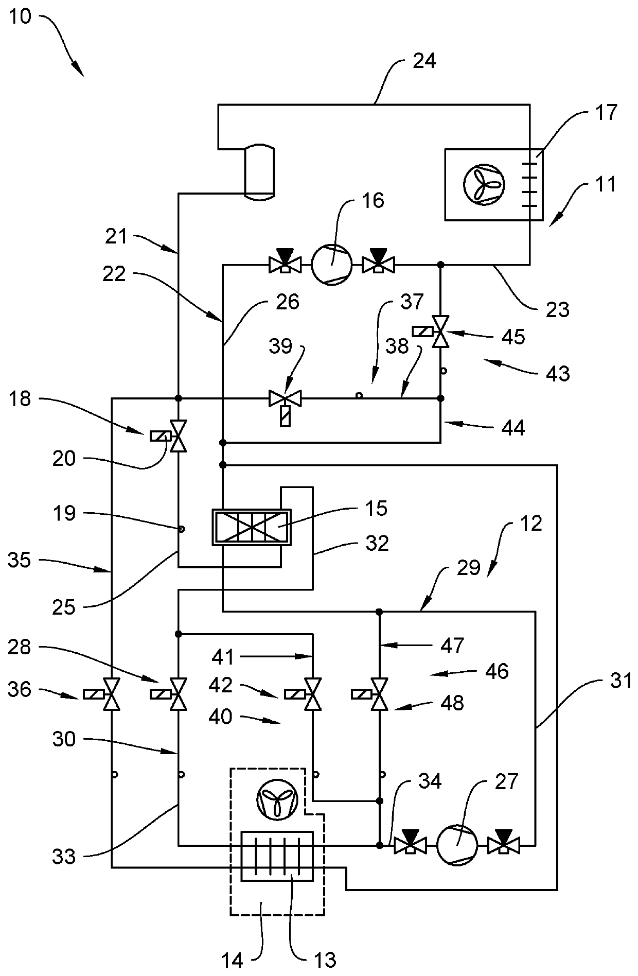
[0034]The first cooling circuit 11 is realized having a cascading heat exchanger 15, a first compressor 16, a condenser 17 and a first expanding element 18. In the first cooling circuit 11, a first refrigerant can be circulated by operating the first compressor 16. The first expanding element 18 is made of a throttle 19 and a magnetic valve 20. All other expanding elements of the cascading cooling device 10 can be realized accordingly. The first cooling circuit 11 comprises a high-pressure side 21, which passes from the first compressor 16 to the first expanding element 18 in the flow direction of the first refrigerant, as well as a low-pressure side 22, which passes from the first expanding element 18 to the first compressor 16. The first refrigerant is gaseous and has a comparatively high temperature in a tube section 23 extending from the first compressor 16 to the condenser 17. The first refrigerant, which is compressed by the first compressor 16, streams in the first cooling ci...


PUM


Abstract

A method for conditioning a fluid in a temperature-insulated test space and a test space of a test chamber for receiving test materials are provided. A particular temperature range within the test space is provided by a cascading cooling device having a first cooling circuit a cascading heat exchanger, a first compressor, a condenser and a first expanding element, and a second cooling circuit, a heat exchanger, a second compressor, the cascading heat exchanger and a second expanding element, said cascading heat exchanger cooled by the first cooling circuit, said heat exchanger subsequently cooled by a bypass passing through the heat exchanger and bridging the cascading heat exchanger, said first compressor being turned off, a first refrigerant conducted and condensed in a gaseous state in the cascading heat exchanger on a low-pressure side of the bypass.

Description

[0001]This application incorporates by reference the disclosure of European Patent Application No. 18178627.8 filed on Jun. 19, 2018.FIELD OF THE INVENTION[0002]The invention relates to a method and a test chamber for conditioning a fluid, particularly air, comprising a temperature-insulated test space for receiving test materials, said test space being sealable against an environment, a temperature ranging from −60° C. to +180° C. in temperature being realized within the test space by means of a cascading cooling device of a temperature control device of the test chamber, having a first cooling circuit having a first refrigerant, a cascading heat exchanger, a first compressor, a condenser and a first expanding element, and having a second cooling circuit having a second refrigerant, a heat exchanger arranged in the test space, a second compressor, the cascading heat exchanger and a second expanding element, said cascading heat exchanger being cooled by the first cooling circuit.BAC...

Claims


Application Information

Patent Timeline
Patent Type & Authority Applications(United States)
IPC IPC(8): F25B7/00F25B29/00F25B41/04F25B49/02F25B41/06
CPCF25B7/00F25B29/003F25B41/046F25B2300/00F25B2600/21F25B49/02F25B41/062G01N17/002F25B2400/01F25B2400/0409
Inventor HAACK, CHRISTIANZAHRT, YANNIKREUSCHEL, DENNISZINNKANN, ANDREBELLET, PASCAL
Owner WEISS TECH GMBH
Why Eureka
Try Eureka