
Test apparatus and method for characterizing a device under test

a test apparatus and device technology, applied in the field of test apparatus and method for characterizing a device under test, can solve the problems of complex high-dimensional optimization problem, time-consuming and easy to misunderstand process, and the value of unchanged variables and measurement conditions tends to not be documented well, so as to improve the probability of detection of errors, improve the effect of practical relevance and easy analysis

Active Publication Date: 2019-12-05
ADVANTEST CORP
View PDF0 Cites 14 Cited by
  • Summary
  • Abstract
  • Description
  • Claims
  • Application Information

AI Technical Summary

Benefits of technology

The proposed approach of random test case generation has several benefits. Firstly, errors are more likely to occur when using a deterministic approach, so using a random approach increases the likelihood of detecting errors. Secondly, errors are usually dependent on multiple variables, so filling the variable space with test cases increases the likelihood of detecting errors. Thirdly, if a test is aborted during execution, a random test case generation can cover the area where the error occurred and allow for easier detection and fixing of errors. Additionally, the data analysis unit can project any relevant information about the device under test onto the space of variables, which can help identify dependencies between variables. The data storage unit can also store the test data after each test case is performed to prevent data loss.

Problems solved by technology

Understanding the performance limits of today's complex devices and programming and calibrating them such that they meet multiple specifications under all allowed operating and input conditions, while consuming minimum power, is a very complicated high-dimensional optimization problem, jointly faced by designers, firmware engineers, system engineers, and test engineers.
This process is time-consuming and prone to misunderstandings.
This approach has several, increasingly important limitationsTime consuming: Each iteration involves writing a new test, debugging it, and finally running it, before results are available.Error prone: Writing individual tests allows individual errors to creep in.Ambiguous: Axis labels tend to be inconsistent.
Values of unchanged variables and measurement conditions tend not be documented well.Insufficient: The large number of variables (e.g. stimulus settings, device settings, operations conditions) renders a full N-dimensional sweep over all involved variables impossible.
Engineers may restrict themselves to a small set of predetermined plots f(x), f(x, y), or with low-dimensional sweeps, where the remaining variables have predefined values.Partial results: When a nested loop aborts (power outage, contact problems, device dies, crash), chances are that the outmost loop variable has not yet changed and results are mostly unusable.Fools machine learning algorithms: Because defined tests reflect the engineers understanding of likely dependencies, machine learning algorithm can only operate on highly biased data, potentially leading to self-fulfilling prophecies.
Nonetheless, a huge amount of tests is aborted or interrupted during processing.
Using the proposed approach, errors occur more often since the variable space is filled more quickly and it is more likely to hit or to detect an error (in the same time) when compared to the deterministic approaches.
Moreover, since errors are usually dependent on more than one variable, the variation of (nearly) all variables within consecutive test cases increases the probability to detect errors (in the same time) when compared to a deterministic approach.
This may be an error within the device under test which, for example, typically occurs at a certain temperature, voltage or electric current of a processing unit of the device under test.
However, the human perception may have difficulties to reveal dependencies, without technical support, in more than three dimensions.
Therefore, even a reduced test time, for example due to a scenario incurring or causing an error in the device under test, or a power failure, may result in a data set revealing sufficient information to find dependencies within the variables.

Method used


Image

  • Test apparatus and method for characterizing a device under test
  • Test apparatus and method for characterizing a device under test
  • Test apparatus and method for characterizing a device under test

Examples


Embodiment Construction

[0036]In the following, embodiments of the invention will be described in further detail. Elements shown in the respective figures having the same or a similar functionality will have associated therewith the same reference signs.

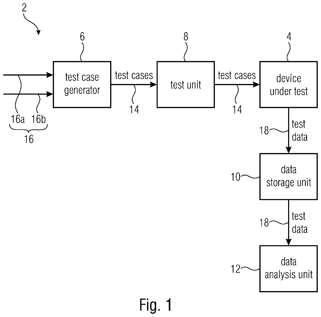
[0037]FIG. 1 shows a schematic block diagram of a test apparatus 2 for characterizing a device under test 4. The test apparatus 2 comprises a test case generator 6, a test unit 8, a data storage unit 10, and a data analysis unit 12. The test case generator 6 is configured to randomly generate a plurality of test cases 14, wherein a test case 14 comprises values of one or more input variables 16a, 16 of a set of input variables 16. The test unit 8 is configured to perform the plurality of test cases 14 on the device under test 4. Moreover, the data storage unit may store sets of test data 18, wherein the sets of test data 18 are associated to the test cases 14 and wherein the sets of test data 18 comprise values of input variables of a respective test case a...


PUM


Abstract

A test apparatus for characterizing a device under test includes a test case generator, a test unit, a data storage unit, and a data analysis unit. The test case generator is configured to randomly generate a plurality of test cases, which include values of one or more input variables of a set of input variables. The test unit is configured to perform the plurality of test cases on the device under test. The data storage unit may store sets of test data, which are associated to the test cases and include values of input variables of a respective test case and corresponding values of output variables of the device under test related to the respective test case. The data analysis unit may further analyze the test data and is further configured to determine dependencies within a subset of variables of the test data to characterize the device under test.

Description

CROSS-REFERENCES TO RELATED APPLICATIONS[0001]This application is a continuation of copending International Application No. PCT / EP2017 / 055370, filed Mar. 7, 2017, which is incorporated herein by reference in its entirety.BACKGROUND OF THE INVENTION[0002]Understanding the performance limits of today's complex devices and programming and calibrating them such that they meet multiple specifications under all allowed operating and input conditions, while consuming minimum power, is a very complicated high-dimensional optimization problem, jointly faced by designers, firmware engineers, system engineers, and test engineers.[0003]Current practice is that test engineers create and run a series of predetermined tests in response to specific information requests from designers and firmware & system engineers. When results are surprising, new tests are created to return additional requested plots. This process is time-consuming and prone to misunderstandings.[0004]The current practice is a se...

Claims


Application Information

Patent Timeline
Patent Type & Authority Applications(United States)
IPC IPC(8): G06F11/36G06F11/263
CPCG06F11/3692G06F11/263G06F11/3688G06F11/3684G06F11/22G06F11/3672
Inventor RIVOIR, JOCHEN
Owner ADVANTEST CORP
Learn More