
Data processing apparatus and prefetch method

a data processing apparatus and prefetching technology, applied in computing models, biological models, instruments, etc., can solve the problems of neural networks having a complicated structure and increasing the cost of the system, and achieve the effect of increasing the block address spa

Active Publication Date: 2019-11-28
HITACHI LTD
View PDF1 Cites 10 Cited by
  • Summary
  • Abstract
  • Description
  • Claims
  • Application Information

AI Technical Summary

Benefits of technology

The present invention provides a data processing apparatus that can determine an area to be prefetched while accommodating an increase in a block address space. This means that the apparatus can determine which part of the data should be prefetched based on the current needs of the system. This helps to improve the efficiency of the data processing system and reduces the time taken for data transfer.

Problems solved by technology

However, it is necessary to use many computing machines for which a total main storage capacity exceeds a data size, resulting in cost increase of the system.
Therefore, a mechanism that retains data with a high access frequency is implemented in the in memory database to perform writes and reads for optimizing data placement; however, this involves increasing memory hierarchies and it is, therefore, necessary to greatly alter a data placement mechanism.
In the well-known example of providing a function to perform machine learning on patterns of previous writes and reads to and from a storage and using the learned patterns in prefetch on the basis of a prediction result, predicting data to be accessed in the future in blocks requires a large amounts of data and powerful computing machine resources to cause neural networks having a complicated structure to learn the patterns since the storage has a huge block address space.
Moreover, since the structure of optimum neural networks varies depending on an applied field, trials and errors including devising new models are necessary in the machine learning.

Method used


Image

  • Data processing apparatus and prefetch method
  • Data processing apparatus and prefetch method
  • Data processing apparatus and prefetch method

Examples


first embodiment

[0031]FIG. 1 is a block diagram depicting a configuration of a data processing apparatus according to a first embodiment.

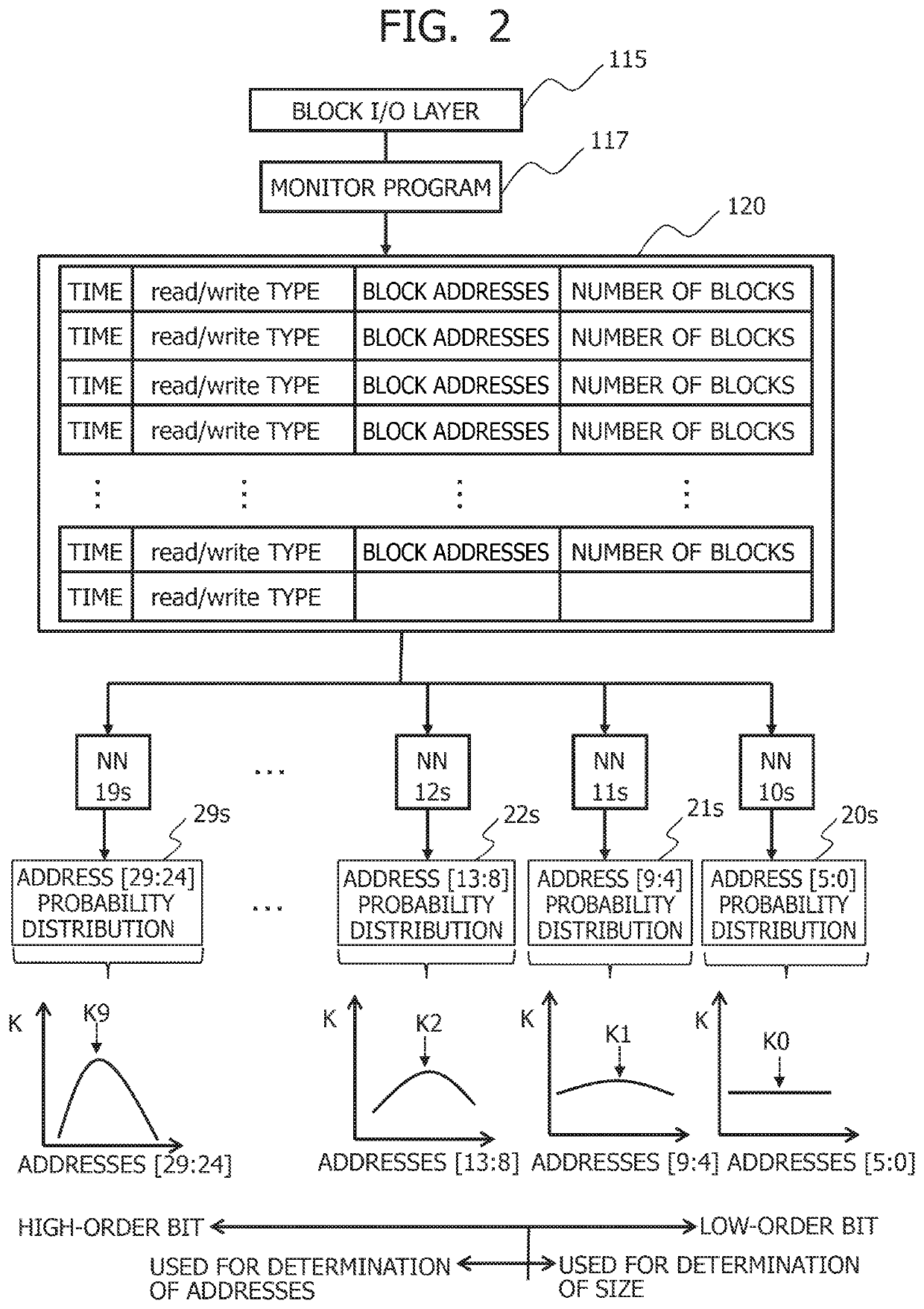
[0032]In FIG. 1, the data processing apparatus is configured with a data analysis server 1, a storage device 2, and a neural network management system 3. The data analysis server 1 analyzes large-scale data stored in the storage device 2. The neural network management system 3 manages neural networks 10a to 19a, 10b to 19b, . . . , and 10z to 19z that have been made to perform machine learning on I / O trace data 12 for each of bit ranges into which block addresses of a storage are split. Block addresses used in previous reads or writes are recorded in the I / O trace data 12.

[0033]The storage device 2 stores the large-scale data to be analyzed by the data analysis server 1. At this time, the storage device 2 can perform storage caching on data to be read or to be written. The storage device 2 herein splits block addresses into a plurality of bit ranges on the basis o...

second embodiment

[0096]FIG. 10 is a block diagram depicting a configuration of a data processing apparatus according to a second embodiment.

[0097]The data processing apparatus of FIG. 10 is configured with a storage device 2A as an alternative to the storage device 2 and the neural network management system 3 of FIG. 1. The storage device 2 is configured with a machine learning computing machine 132A and an I / O trace data storage 9 additionally to the configuration of the storage device 2 of FIG. 1. The I / O trace data storage 9 stores the I / O trace data 12 in the column store format of FIG. 7. A storage class memory 125A in the storage device 2A is configured with a neural network management area 505 additionally to the storage area 501, the cache areas 502 and 503, and the spare area 504 of FIG. 5. The neural network management area 505 can be configured similarly to the neural network management area 134 of FIG. 1.

[0098]The I / O trace data 12 that is learning data is collected by the storage contro...

third embodiment

[0101]FIG. 11 is a block diagram depicting a configuration of a data processing apparatus according to a third embodiment.

[0102]The data processing apparatus of FIG. 11 is configured with a data analysis server 1B, a storage device 2B, and a neural network management system 3B.

[0103]The data analysis server 1B is configured with the statistical analysis software 111, the DB client 112, the database management system 113, the file system 114, the block I / O layer 115, a device driver 116B, a storage class memory 117, and a machine learning processor 118.

[0104]The device driver 116B is configured with the prediction accuracy determination section 122, the predicted value determination section 123, the prefetch issuance section 124, and the prediction model 127 of FIG. 1. The storage class memory 117 is configured with the cache area 503 of FIG. 5. The storage class memory 117 may be also configured with a main storage area and a spare area in addition to the cache area 503. The machine...


PUM


Abstract

An area for prefetching is determined while accommodating an increase in a block address space. A prediction model predicts prefetch addresses for each of bit ranges into which block addresses are split by using a plurality of neural networks assuming charge of the different bit ranges having performed machine learning on I / O trace data, a prediction accuracy determination section determines a size of an area for prefetching on the basis of addresses in the bit range for which prediction accuracy in prefetch is lower than a predetermined value, a predicted value determination section determines addresses of the area for prefetching on the basis of addresses in the bit range for which the prediction accuracy in the prefetch is equal to or higher than the predetermined value, and a prefetch issuance section caches data in the area for prefetching in a storage class memory from a NAND flash memory.

Description

BACKGROUND OF THE INVENTION1. Field of the Invention[0001]The present invention relates to a data processing apparatus and a prefetch method applicable to a storage class memory.2. Description of the Related Art[0002]A storage class memory is a new memory that fills a memory hierarchy gap in a computing machine, that is, a gap between a main storage device configured with a DRAM and a storage device configured with a NAND flash memory in access time, or more specifically a gap to the extent that the main storage device is approximately 1000 times shorter in access time than the storage device. For example, Intel and Micron released 3D XPoint Technology that is a mass-storage nonvolatile memory technology that enables the use of a mass-storage nonvolatile memory as a storage class memory. The technology can realize a nonvolatile memory having a life 1000 times longer than that of a NAND flash memory, faster than the NAND flash memory, having a capacity ten times larger than that of a...

Claims


Application Information

Patent Timeline
IPC IPC(8): G06F12/0862G06N3/08G06N7/00
CPCG06F12/0862G06F2212/1041G06F2212/214G06F2212/222G06F2212/313G06F12/0868G06F2212/461G06F2212/466G06F2212/283G06F2212/6024G06N3/08G06N3/047G06F12/0246G06F16/903G06N7/00
Inventor SAEKI, YUJIBABA, TAKASHIGE
Owner HITACHI LTD
Learn More