
Multi Frequency Monitor for Detecting Ionospheric and Tropospheric Disturbances

a technology of ionospheric and tropospheric disturbances and multi-frequency monitors, which is applied in the direction of satellite radio beaconing, measurement devices, instruments, etc., can solve the problems of significant differences in propagation delay, correlation errors, and aircraft airborne receivers and ground stations to be affected by significantly different propagation delays. , to achieve the effect of eliminating receiver and satellite clock errors

Inactive Publication Date: 2019-11-28
INDRA NAVIA AS
View PDF0 Cites 4 Cited by
  • Summary
  • Abstract
  • Description
  • Claims
  • Application Information

AI Technical Summary

Benefits of technology

The patent describes a method for calculating carrier-phase double differences and Geometry Free Double Differences to estimate ambiguities and remove integer ambiguities. This method helps to eliminate errors caused by receiver and satellite clock errors, providing more accurate data.

Problems solved by technology

Correlated errors are typically errors due to ionospheric delay, tropospheric delay, satellite clock and orbit parameter inaccuracy.
One such condition is deflection of the satellite signal in the ionosphere, causing propagation delays.
However, disturbances in the ionosphere may cause the aircraft's Airborne Receiver and the Ground Station to be affected by significantly different propagation delays.
Previous solutions using phase measurements to monitor for ionospheric gradients were prone to several problems.
One of the problems is if the tropospheric gradient and ionospheric gradient impact the phase measurements in opposite directions, part or all of the ionospheric delay may become invisible to the ionospheric gradient monitor, confounding the monitor.
Another problem is when there is no ionospheric gradient to detect, but a tropospheric gradient is present, this could falsely trigger the monitor.
This could cause the monitor to issue false alarms, which could in turn cause violation of system level continuity requirements, which are also important for flight safety.
Other solutions resolve the problems related to confounding and false alerts, but has some practical implementation issues, such as requiring longer baselines, with a wider spread of receivers, which could be problematic on many airports.

Method used


Image

  • Multi Frequency Monitor for Detecting Ionospheric and Tropospheric Disturbances
  • Multi Frequency Monitor for Detecting Ionospheric and Tropospheric Disturbances
  • Multi Frequency Monitor for Detecting Ionospheric and Tropospheric Disturbances

Examples


Embodiment Construction

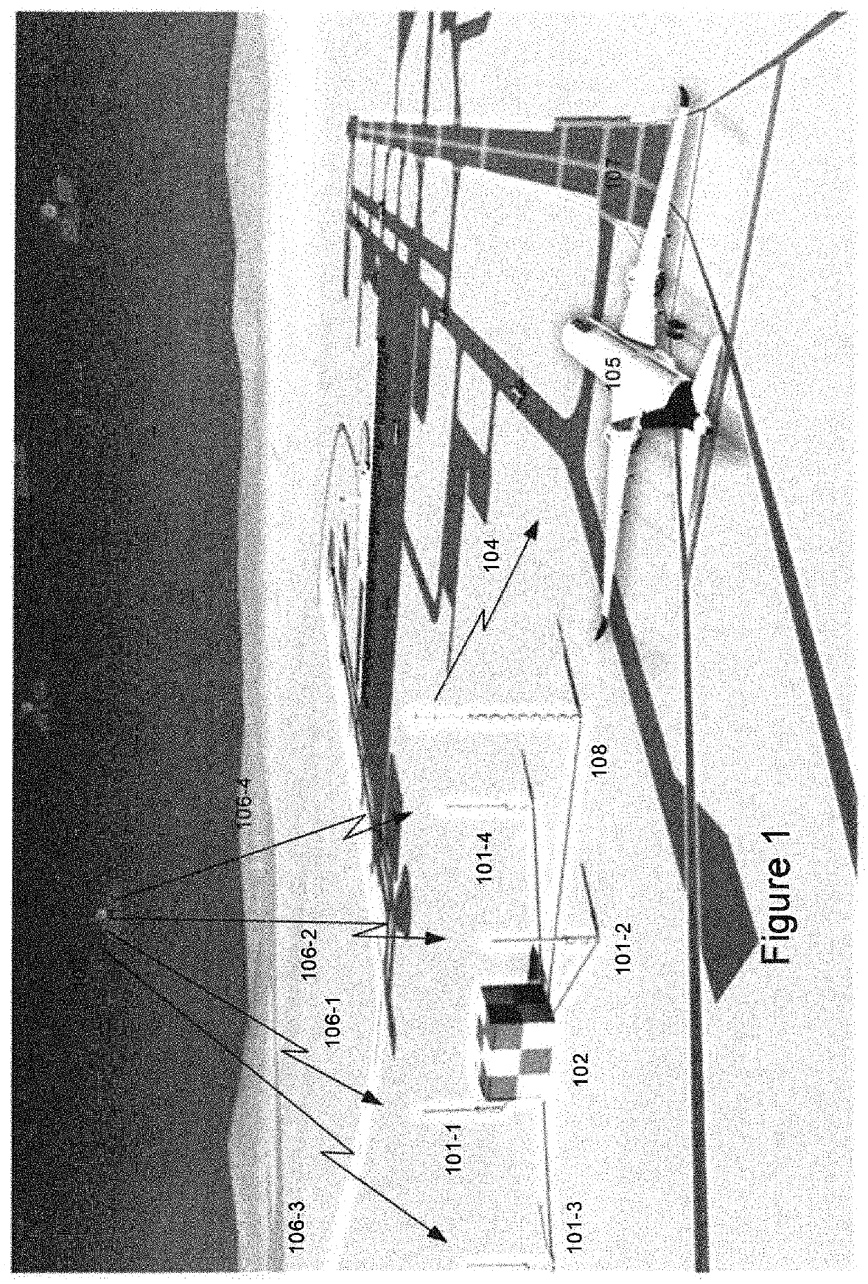
[0020]One of the objectives of the invention is separating ionospheric and tropospheric effect on Ranging Source phase measurements, mitigating the problems related to confounding and significantly reducing the problems of false alerts due to tropospheric effects in ionospheric gradient monitoring. The Ranging Source is a source of Global Navigation Satellite System (GNSS) signal. The invention also enables use of relatively short baselines, in the order of a few hundred meters, reducing civil works and infrastructure costs in comparison with that required to implement GBAS Ground Stations with longer baselines. Furthermore, it enables the use of GNSS receivers with no assurance level or lower assurance level than would be required for the particular application, such as in this case aircraft approach, landing and rollout, in concert with a receiver with sufficient assurance level, but fewer observables.

[0021]FIG. 1 shows an example of an embodiment of the GBAS application with a Gr...


PUM


Abstract

System and method for a Ground Based Augmentation System (GBAS) for detecting ionospheric and tropospheric disturbances using Multi Frequency Monitor. Receiving signals from a plurality of receiver pairs and determining a monitor measurement of tropospheric delay variation using data from at least one pair of the plurality of receivers. Determining a monitor measurement of the sum of tropospheric and the sum of ionospheric delay variations using data from the at least one pair of the plurality of receivers. Combining monitor measurements of tropospheric delay variations and of ionospheric delay variations into an ionospheric delay estimate.

Description

RELATED APPLICATIONS[0001]This application claims the benefit of Norway Application No. 20180681, filed May 14, 2018 which is hereby incorporated by reference in its entirety.TECHNICAL FIELD[0002]The present invention relates to a Ground Based Augmentation System for augmentation of satellite navigation constellations for use in aircraft operations, and problems related to ionospheric effects, and in particular for detecting ionospheric anomalies in for the Ground Based Augmentation System (GBAS).BACKGROUND ART[0003]The Ground Based Augmentation System (GBAS) Approach Service Type D (GAST D) standard shares the mitigation of an ionospheric gradient threat between the ground and Airborne Receivers. This leads to the need for an Ionospheric Gradient Monitor (IGM) located in a Ground Station in order to ensure that the integrity of the system is not compromised in the presence of an ionospheric gradient. A monitor in this context can be viewed as a set of processing steps based on sign...

Claims


Application Information

Patent Timeline
Patent Type & Authority Applications(United States)
IPC IPC(8): G01S19/07
CPCG01S19/15G01S19/074G01S19/07G01S19/23G01S19/25G01S19/42G01S19/44G01S19/072
Inventor PEDERSEN TOPLAND, MORTENSTAKKELAND, MORTENLAVIK, LINDA
Owner INDRA NAVIA AS
Learn More