Eureka AIR delivers breakthrough ideas for toughest innovation challenges, trusted by R&D personnel around the world.

Long baseline satellite formation GNSS relative positioning method based on ambiguity fixing

A technology with fixed ambiguity and relative positioning, which can be used in satellite radio beacon positioning systems, radio wave measurement systems, measurement devices, etc., and can solve the problem of low relative positioning accuracy.

Active Publication Date: 2016-03-02
NAT UNIV OF DEFENSE TECH
View PDF5 Cites 33 Cited by
  • Summary
  • Abstract
  • Description
  • Claims
  • Application Information

AI Technical Summary

Problems solved by technology

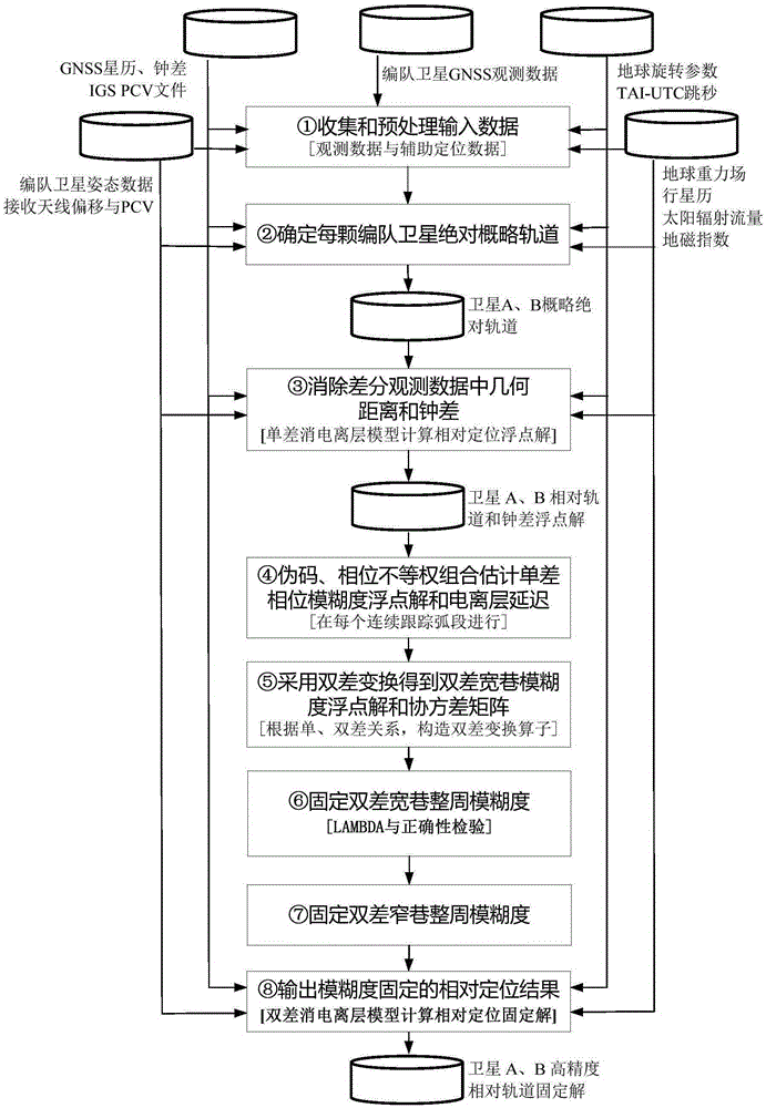
[0005] The technical problem to be solved by the present invention is: Aiming at the problem that the relative positioning accuracy is not high caused by the fixed ambiguity in the traditional long-baseline satellite formation GNSS relative positioning method, which strongly depends on the pseudocode, a long-baseline satellite formation GNSS with fixed ambiguity is proposed The relative positioning method fixes the ambiguity by eliminating the geometric distance in the differential observation data, the pseudo-code after the clock difference, and the unequal weight combination of the phase, avoiding the pseudo-code and phase in the traditional method M-W combination to be combined with equal weights, and improving the ambiguity. Success rate and accuracy of relative positioning results

Method used


Image

  • Long baseline satellite formation GNSS relative positioning method based on ambiguity fixing
  • Long baseline satellite formation GNSS relative positioning method based on ambiguity fixing
  • Long baseline satellite formation GNSS relative positioning method based on ambiguity fixing

Examples


Embodiment Construction

[0088] The present invention will be further introduced below in conjunction with the accompanying drawings. Taking the GNSS relative positioning of the GRACE satellite formation as an example, the inter-satellite distance of the formation in January 2006 was about 140 kilometers, which is a typical long-baseline satellite formation. The in-orbit measurement data of 7 days from February 1 to 7, 2006 were selected. Such as figure 1 As shown, a kind of ambiguity fixed long baseline satellite formation GNSS relative positioning method of the present invention comprises the following steps:

[0089] In the first step, the input data is collected and preprocessed.

[0090] Collect observational data from satellite platforms and ancillary data from websites (see Table 1). Preprocess the GNSS observation data of the 7-day GRACE satellite formation, mark outliers and cycle slips, save the preprocessed daily data in the form of text files, and output the preprocessed GNSS observation...


PUM


Abstract

A long baseline satellite formation GNSS relative positioning method based on ambiguity fixing is provided in order to improve the success rate of ambiguity fixing and the accuracy of relative positioning results. According to the technical scheme, the method comprises the following steps: first, collecting and pre-processing input data, and determining the absolute general orbit of a formation satellite; then, eliminating the geometric distance and clock error in differential observation data, estimating a single-difference phase ambiguity float solution and a single-difference ionosphere delay parameter, carrying out double-difference transform to get a double-difference wide-lane ambiguity float solution and a covariance matrix, and fixing the double-difference wide-lane integer ambiguity and the double-difference narrow-lane integer ambiguity; and finally, outputting the relative positioning result of ambiguity fixing. By adopting the method of the invention, the problem that ambiguity fixing strongly depends on a pseudo code with low observation precision due to equally-weighted pseudo code and phase processing in M-W combination in the traditional method is avoided, the success rate of long baseline satellite formation GNSS relative positioning ambiguity fixing and the accuracy of final relative positioning results are improved, calculation is stable, and the reliability of relative positioning results is improved.

Description

technical field [0001] The invention relates to a relative positioning method of a long baseline satellite formation in the field of aerospace survey, in particular to a relative positioning method of a long baseline satellite formation using a global navigation satellite system GNSS (Global Navigation Satellite System) measurement means and an ambiguity fixing strategy. Background technique [0002] Space-borne GNSS adopts star-to-star tracking method. By installing GNSS receivers on satellites flying in formation and using carrier phase difference GNSS technology, it can eliminate or weaken the influence of some common errors, and can provide millimeter-level relative positioning accuracy. Space-borne GNSS has the advantages of all-weather, continuity, high precision, and wide space-time coverage. The use of space-borne GNSS to determine the relative position of formation satellites with high precision has been successfully applied to tasks such as distributed radar interfe...

Claims


Application Information

Patent Timeline
IPC IPC(8): G01S19/51G01S19/41G01S19/44
CPCG01S19/41G01S19/44G01S19/51
Inventor 谷德峰申镇孙蕾易东云涂佳刘俊宏鞠冰
Owner NAT UNIV OF DEFENSE TECH
Why Eureka
Eureka Blog
Learn More