
System and process for persistent marking of flexo plates and plates marked therewith

a technology of flexo plates and processes, applied in the field of system and process for persistent marking of flexo plates and plates marked therewith, can solve the problems of limited use of workflow markings, if used at all, and the inability to fully utilize the possibility of this feature, and achieve the effect of increasing the siz

Active Publication Date: 2019-11-21
ESKO GRAPHICS IMAGING
View PDF0 Cites 12 Cited by
  • Summary
  • Abstract
  • Description
  • Claims
  • Application Information

AI Technical Summary

Benefits of technology

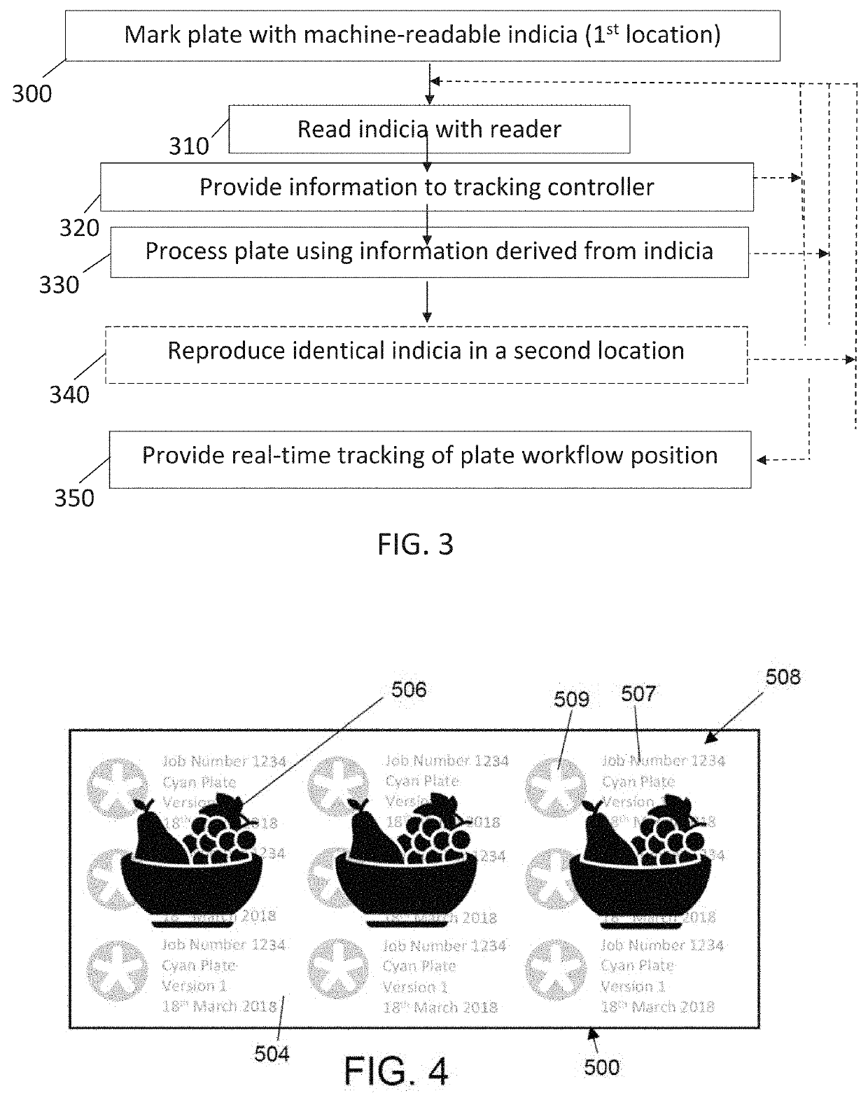
The patent text describes a system where processing equipment is provided with a scanner or reader to get information about the plates they are processing. This information is used to set the parameters for the processing step. The reader can be a mobile device like a phone or a computer. The connection between the reader and the controller can be wired or wireless. The controller translates the information from the reader into the information needed to set the parameters. The indicia, which may be a code like a QR or barcode, can contain information like a process identifier or a unique plate identifier. This unique identifier can be used to track the plate or identify it with a mobile device. The technical effect of this system is to streamline the processing workflow, make it easier to set the parameters, and improve production efficiency.

Problems solved by technology

However, the possibilities of this feature are typically not fully utilized.
Consequently, the use of workflow markings, if used at all, is typically limited to only general information, because attaching equipment-specific parameters to a plate that may be processed on different devices with different parameter settings may not be efficient or useful.
Consequently, human errors may cause a certain percentage of failure, resulting in plate loss, rework and loss of money.
One limitation of prior art marking methods for flexo plates is that they typically only contain a small amount of information that does not support the entire plate workflow.

Method used


Image

  • System and process for persistent marking of flexo plates and plates marked therewith
  • System and process for persistent marking of flexo plates and plates marked therewith
  • System and process for persistent marking of flexo plates and plates marked therewith

Examples


Embodiment Construction

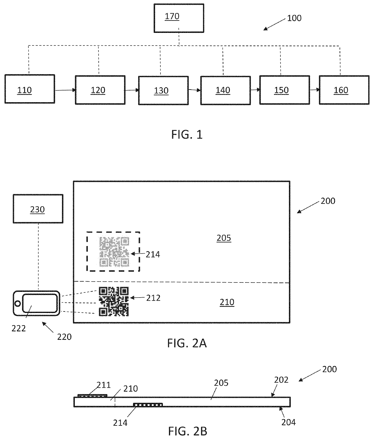
[0063]Referring now to the figures, FIG. 1 schematically illustrates a workflow 100 having a plurality of process machines 110, 120, etc. each configured to perform one or more process steps in the workflow of creating a printing plate.

[0064]As depicted in FIGS. 2A and 2B, one aspect of the invention provides a marking method and structure for flexographic printing plates 200 and their precursor states, which enables the association of up-to-all process-relevant information to the plate itself by attachment of indicia 212, 214 to the plate, and thereby enables controlling up-to-all process stages using this information. Preferably, the processing machines used for the plates are also configured with or in communication with a reader 220 configured to read the marks, and configured to receive process parameters required for the plate to be processed and to report the status of plates being processed to a central control computer 170, based upon information derived from reading the ma...


PUM


Abstract

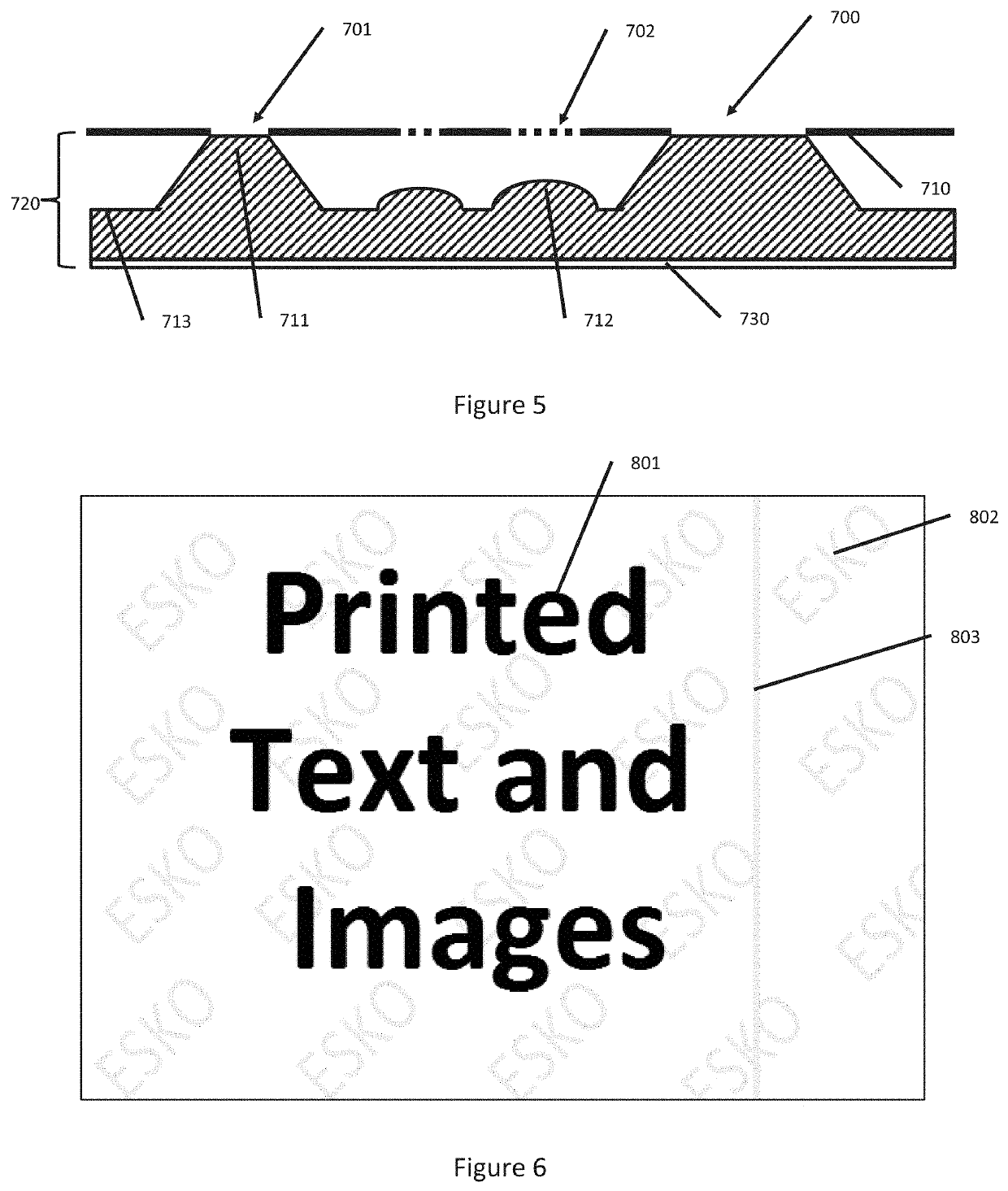
Systems and processes for making a flexo plate, and plates made thereby. Non-printing indicia defined by areas of presence and absence of polymer in the plate floor created using microdots imaged during a LAMS layer imaging step are readable downstream of the washing or other non-cured-polymer-removal step but not to print in the printing step. The non-printing indicia may define a repeating pattern of alphanumeric characters, non-text graphics, or a combination thereof. A difference in growth of plate structures corresponding to different types of microdots may be used for characterizing processing conditions.

Description

[0001]This application is a continuation-in-part of PCT Application Ser. No. PCT / EP19 / 052536, filed 1 Feb. 2019, which claims priority to U.S. Provisional Patent Application No. 62 / 653,972, filed 6 Apr. 2018, both titled “METHOD FOR PERSISTENT MARKING OF FLEXO PLATES WITH WORKFLOW INFORMATION AND PLATES MARKED THEREWITH,” the contents of both of which are incorporated herein by reference in their entirety for all purposes.BACKGROUND OF THE INVENTION[0002]Most contemporary raster image processing (RIP) software, such as, for example, the RIP available with ESKO Automation Engine software, sold by Esko Software BVBA of Ghent, Belgium, allows creation of Barcodes or QR-codes, which can be added to the image information on a flexographic printing plate. However, the possibilities of this feature are typically not fully utilized.[0003]A typical flexo plate workflow may comprise the following steps:[0004]1. Processing image information, using a raster image processor, at a certain screen ...

Claims


Application Information

Patent Timeline
IPC IPC(8): B41M1/04B41F13/12B41M3/14B41N1/12
CPCB41F13/12B41M1/04B41N1/12B41M3/14B41P2200/12G03F7/0012G03F7/202G03F7/2022B41C1/00G06K1/121G06K7/1413
Inventor SIEVERS, WOLFGANGTHOMAS, PASCALKLEIN, THOMAS
Owner ESKO GRAPHICS IMAGING
Learn More