
Carbon dioxide treatment of cathodes

a cathode and carbon dioxide technology, applied in the field of cathode particle surface treatment, can solve the problems of high cost of solvent recovery, long production time of finished laminates, and high processing costs of process, and achieve the effects of facilitating a low ph reaction, minimizing elemental dissolution, and enhancing the electrophoretic kinetics of reaction

Active Publication Date: 2019-10-24
UCHICAGO ARGONNE LLC
View PDF1 Cites 4 Cited by
  • Summary
  • Abstract
  • Description
  • Claims
  • Application Information

AI Technical Summary

Benefits of technology

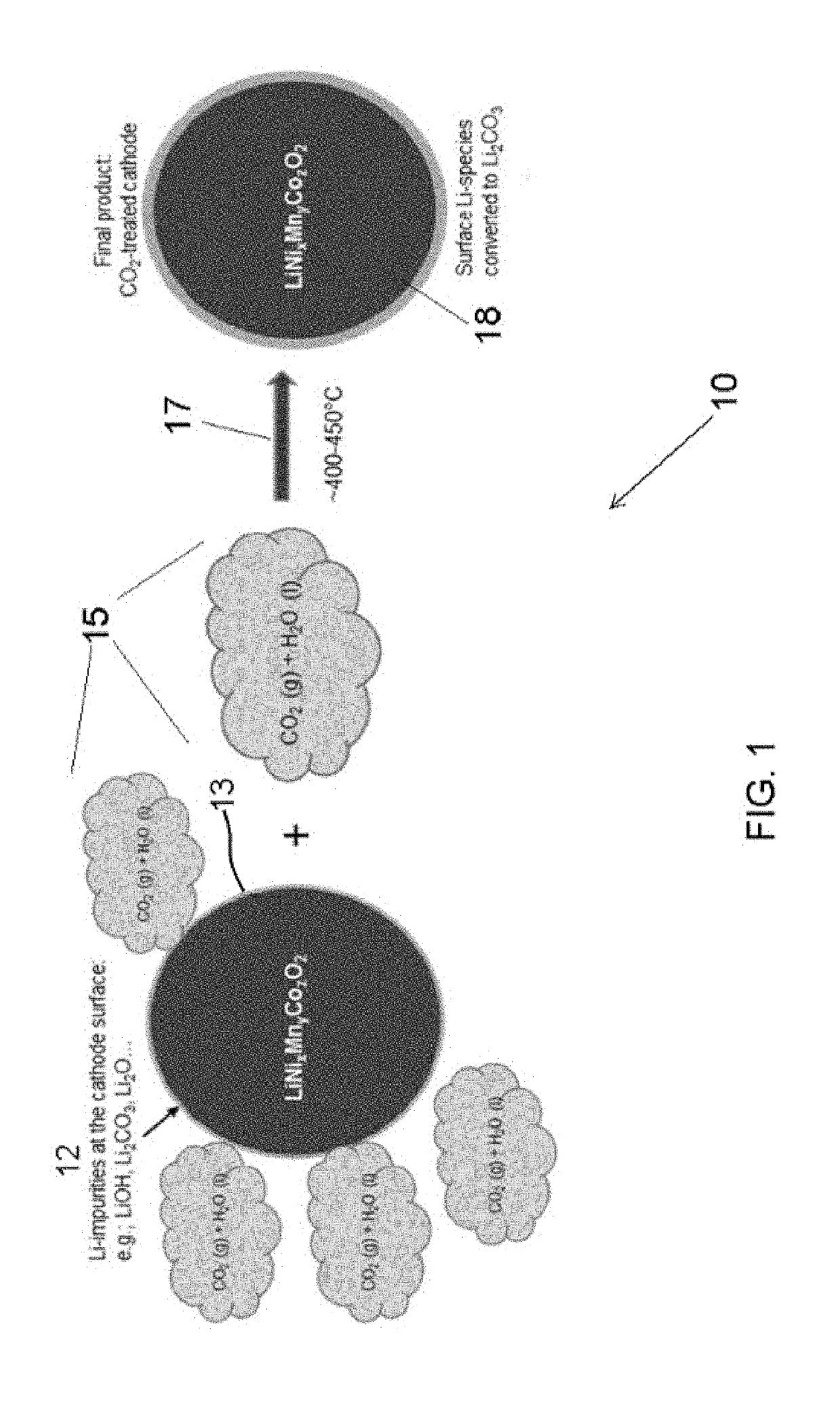
The patent describes a method for producing water-stable cathode particles for use in making lithium-ion batteries. The method involves coating the cathode surface with a lithium carbonate coating using solid carbon dioxide, which protects the cathode during water exposure during battery manufacture. The coated cathode powder can then be pressed or laminated onto a current collector for use in the battery. The invention has several advantages, including protecting the cathode during battery manufacture, improving battery performance, and optimizing current collector coating protocols.

Problems solved by technology

This process is costly given the high boiling point of the hazardous solvent being used.
Recovery of the solvent involves a highly expensive process.
Further, the production time of the finished laminates is lengthy, often exceeding 24 hours.
The aforementioned state of the art processes are very time dependent due to slow reaction rates.
However, water damages the cathode particles, in particular cathode particles comprising nickel, cobalt, and manganese (NMC), due to high lithium ion dissolutions.
Aqueous base technologies suffer from the particles being unstable in water.
These high pH values for the slurry adversely affects the electrophoretic deposition process (e-coat).
This causes damage to the particles.
Many anionic (e.g. polymer based) and cationic (metal based) coatings have been proposed but none of those mitigate the problem.
This results in a weak exposure of the carbon dioxide to all cathode surfaces.
Such agitation means are an added expense.
However, inasmuch as water is super abundant, this process also causes the particles to deteriorate before the final coating is established.
Higher conductivity of the bath results, and this adversely affects the migration as well as the adherence of charged cathode particles (micelles) on aluminum current collector surfaces.
This conversion requires a minimum of 1 month and up to 1 year of exposure, thereby rendering it unreasonably slow for production purposes.
State of the art protocols can not generate stable carbonic acid in a hot and humid environment.

Method used


Image

  • Carbon dioxide treatment of cathodes
  • Carbon dioxide treatment of cathodes

Examples


Embodiment Construction

[0035]The foregoing summary, as well as the following detailed description of certain embodiments of the present invention, will be better understood when read in conjunction with the appended drawings.

[0036]All numeric values are herein assumed to be modified by the term “about”, whether or not explicitly indicated. The term “about” generally refers to a range of numbers that one of skill in the art would consider equivalent to the recited value (e.g., having the same function or result). In many instances, the terms “about” may include numbers that are rounded to the nearest significant figure.

[0037]The recitation of numerical ranges by endpoints includes all numbers within that range (e.g. 1 to 5 includes 1, 1.5, 2, 2.75, 3, 3.80, 4, and 5).

[0038]The following detailed description should be read with reference to the drawings in which similar elements in different drawings are numbered the same. The drawings, which are not necessarily to scale, depict illustrative embodiments and...


PUM


Abstract

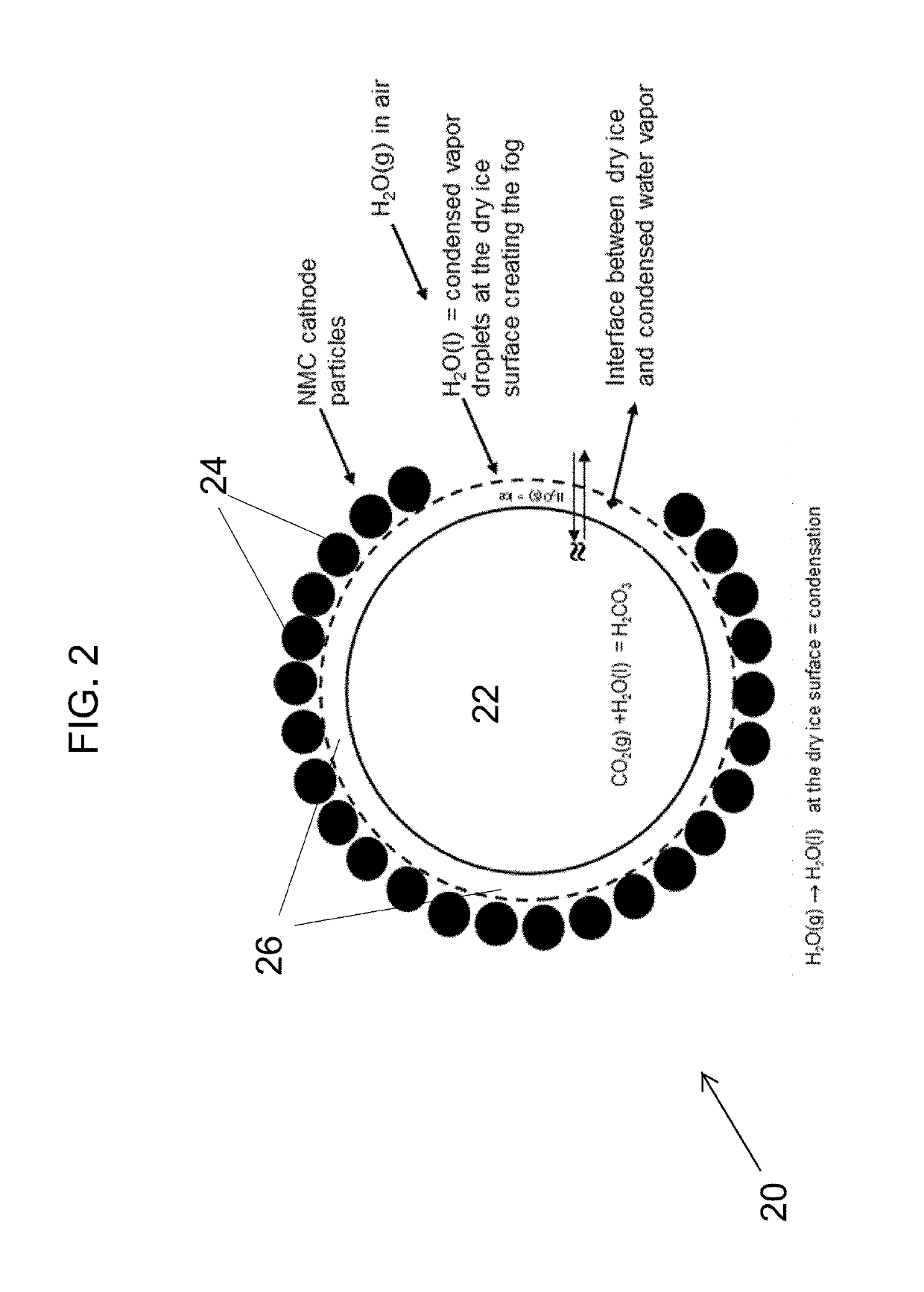
A method for producing water resistant cathodes is discussed. The method uses mixing cathode powder with solid carbon dioxide to create a mixture and heating the mixture to a temperature. The heating occurs for a time sufficient to cause lithium carbonate coatings to form on the powder. A method for coating lithium-containing cathode surfaces is also discussed. This method uses simultaneously sublimating solid CO2 and condensing atmospheric water vapor onto surfaces. Afterwards allowing the lithium to react with the sublimated CO2 for a time sufficient to create a lithium carbonate film on the surface.

Description

CONTRACTUAL ORIGIN OF THE INVENTION[0001]The U.S. Government has rights in this invention pursuant to Contract No. DE-AC02-06CH11357 between the U.S. Department of Energy and UChicago Argonne, LLC, representing Argonne National Laboratory.BACKGROUND OF THE INVENTION1. Field of the Invention[0002]This invention relates to cathode particle surface treatments, and more specifically, this invention relates to a method for improving water stability of cathodes to enable aqueous-based electrode manufacturing.2. Background of the Invention[0003]Lithium-ion cathode materials are processed into electrode laminates by using solvent based slurry coatings, such solvents including N-methylpyrrolidone (NMP). Typically, cathode powders are pressed or otherwise calendered into laminates onto current collectors and dried. Then the laminates are punched out as cathode-electrodes which are then built into batteries. This process is costly given the high boiling point of the hazardous solvent being use...

Claims


Application Information

Patent Timeline
IPC IPC(8): H01M4/36C01G53/00C01D15/08H01M4/58H01M4/525H01M4/505H01M10/0525
CPCC01D15/08H01M4/505H01M4/525H01M10/0525C01G53/50H01M2004/028H01M4/366C01P2004/80C01P2006/40H01M4/5825H01M4/1391H01M4/62H01M4/0471Y02E60/10
Inventor FERIDUN, OZGENUR KAHVECIOGLUKRUMDICK, GREGORY K.
Owner UCHICAGO ARGONNE LLC
Learn More