Counting mechanism

a technology of counting mechanism and cylinder, which is applied in the direction of instruments, volume metering, liquid/fluent solid measurement, etc., can solve the problems of increasing the cost, increasing the risk of malfunction, and insufficient dose delivery, so as to reduce the possibility of failure and reduce the cost of manufacture

Active Publication Date: 2019-10-24
TTP PLC
View PDF0 Cites 4 Cited by
  • Summary
  • Abstract
  • Description
  • Claims
  • Application Information

AI Technical Summary

Benefits of technology

[0020]With the lock out mechanism according to the present invention, a rotatable three part counting mechanism (wherein one of the parts is driven by rotation of the others) may be prevented from further rotation once a predefined number of counts are recorded. The lock out mechanism utilises the fact that the three parts only align once during the lifetime of the device and therefore simultane

Problems solved by technology

Frequently this loss of dose is not visible to the user and therefore may result in an insufficient dose being delivered with possible implications for the effective treatment of a related condition.
This increases the cost and means such devices are more liable to malfunction through failure of one of the many components.
In particular a wide range of counting mechanisms have been proposed to be used with pMDIs including mechanisms with ratchet and pawl mechanisms (US2002139812), face gears (U.S. Pat. No. 8,740,014), kick wheels (U.S. Pat. No. 8,820,318), escapement mechanisms (US2002195102) and helical tracked teeth (US20060231093). pMDI counters have a challenging set of requirements in that they must accurately keep track of the very small reciprocating movement of the actuator st

Method used


Image

  • Counting mechanism
  • Counting mechanism
  • Counting mechanism

Examples


Embodiment Construction

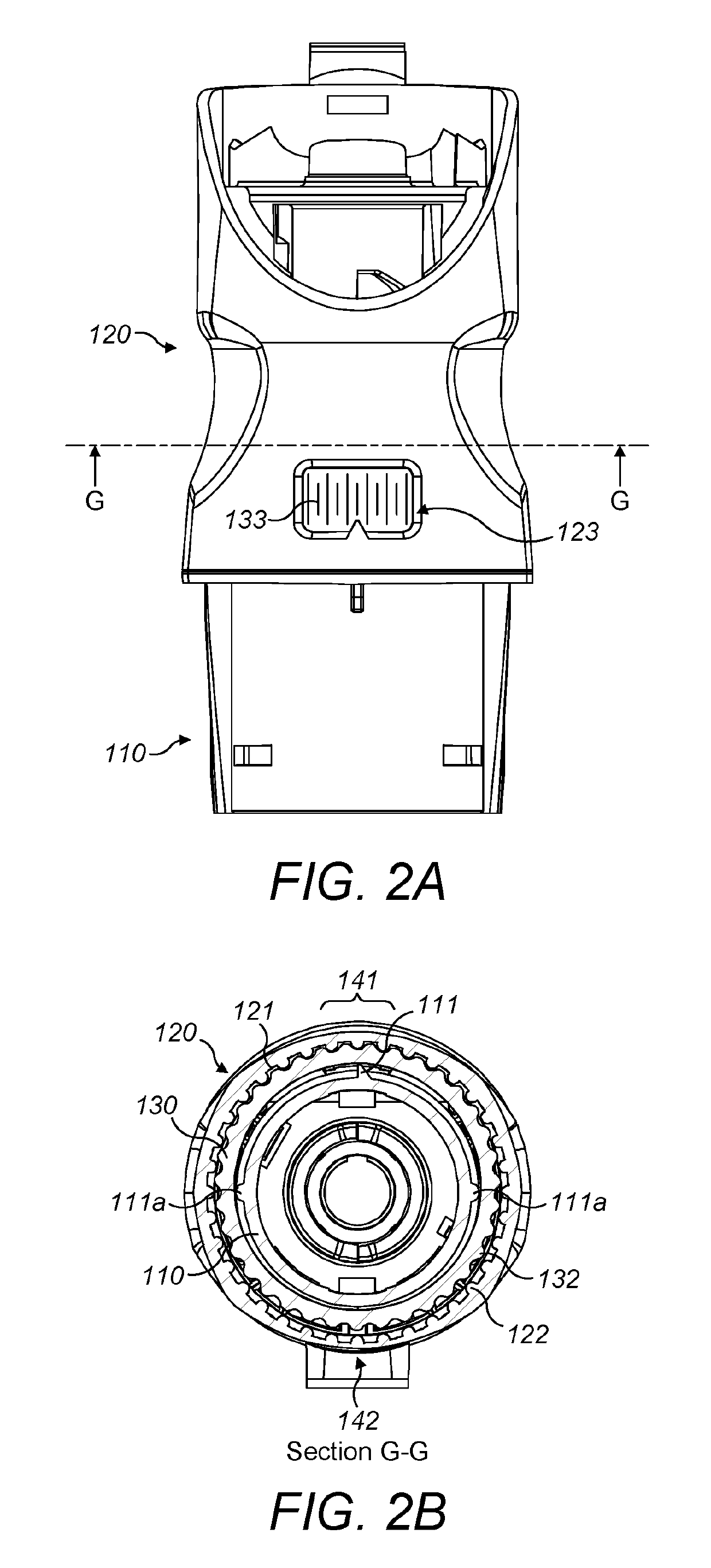
[0035]FIGS. 1A and 1B schematically illustrate a counting mechanism 100 according to the present invention. The counting mechanism 100 comprises a first housing part 110 and a second housing part 120. The second housing part 120 has a curved cross-sectional shape and is rotatable relative to the first housing part 110. The counting mechanism 100 further comprises a counting ring 130 which is positioned between the first 110 and second 120 housing parts. The first housing part 110 has a protrusion 111, shown in the exploded view of FIG. 1A which is positioned so as to abut the counting ring 130 when the mechanism 110 is assembled.

[0036]When assembled the protrusion acts so as to hold the counting ring 111 against the second housing part 120. When the housing parts 110, 120 are rotated the protrusion slides against the surface 131 of the counting ring 130 which drives a rolling movement of the counting ring 130 around the circumference of an opposing curved surface of the second housi...


PUM


Abstract

A counting mechanism (100) for a dispenser comprising: a first and a second housing part (110, 120) that are rotatable relative to each other; and a counting ring (130) disposed between the housing parts. The first housing part has a protrusion (111) which abuts the counting ring, holding a portion of the counting ring in contact with the second housing part. The relative rotation of the housing parts causes the protrusion to slide against the surface of the counting ring to drive a rolling movement of the counting ring around the circumference of the second housing part, such that a predefined rotation of the housing parts produces an incremental rotational displacement between the counting ring and second housing part to record a count. The counting mechanism provides a large gear reduction ratio in a compact form which is straightforward to manufacture and provides an accurate and reliable record of counts.

Description

RELATED APPLICATIONS[0001]The present application is a national stage application under 35 U.S.C. § 371 of International Application No. PCT / GB2017 / 051724, filed 14 Jun. 2017, which claims priority to Great Britain Patent Application No. 1610450.7, filed 15 Jun. 2016. The above referenced applications are hereby incorporated by reference into the present application in their entirety.TECHNICAL FIELD[0002]The present invention relates to a counting mechanism, in particular a counting mechanism for a dispenser or sampler wherein the mechanism may record the number of dispensing counts or sampling counts.BACKGROUND[0003]Counting mechanisms and devices are well known in the art and take many different forms with the common aim of providing means to incrementally count a number of events. Such mechanisms are often incorporated into samplers to record a count of sampling events and dispensers to record a count of dispensing events. A particularly important application of counting mechanis...

Claims


Application Information

Patent Timeline
IPC IPC(8): G06M3/02G06M1/06
CPCG06M3/021G06M1/064G06M3/12A61J7/02A61M15/0073A61M15/0081A61M5/31553G01F11/006A61M2005/3125A61M2205/27
Inventor STRANGE, DANIELBAKER, LAWRENCE
Owner TTP PLC
Why Eureka
Try Eureka