
Method and apparatus for locking a drill guide in a polyaxial hole

a polyaxial hole and drill guide technology, applied in the field of surgical devices, can solve the problems of difficult locking of the screw and jeopardizing the locking capability of the polyaxial hole, and achieve the effect of preventing the plurality of prongs from radially inward deflection

Active Publication Date: 2019-10-17
GLOBUS MEDICAL INC
View PDF0 Cites 5 Cited by
  • Summary
  • Abstract
  • Description
  • Claims
  • Application Information

AI Technical Summary

Benefits of technology

The patent is about a device and method for locking a drill guide in a hole while maintaining the function of the hole. The device includes a hollow outer body with a slot and an inner body with a central channel. A lever is coupled to the inner body through the slot, and when the lever is rotated, the inner body moves along the central axis of the drill guide. The distal end of the inner body prevents the prongs from deflecting radially inward when the inner body is in a lowermost position. The method involves inserting the drill guide into the hole, pushing the distal end of the outer body beyond a shoulder of the hole, and then rotating the lever to move the inner body to a lowermost position. The device and method allow for secure locking of the drill guide without compromising the function of the hole.

Problems solved by technology

However, with such polyaxial holes, locking of the screw may be difficult.
Such a hole cannot be threaded into via a threaded drill guide because doing so would jeopardize the locking capabilities of the polyaxial hole.

Method used


Image

  • Method and apparatus for locking a drill guide in a polyaxial hole
  • Method and apparatus for locking a drill guide in a polyaxial hole
  • Method and apparatus for locking a drill guide in a polyaxial hole

Examples


Embodiment Construction

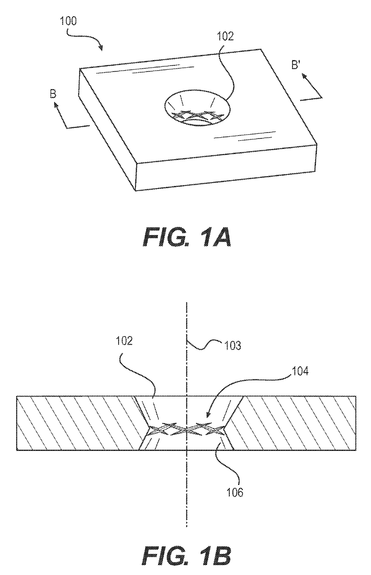
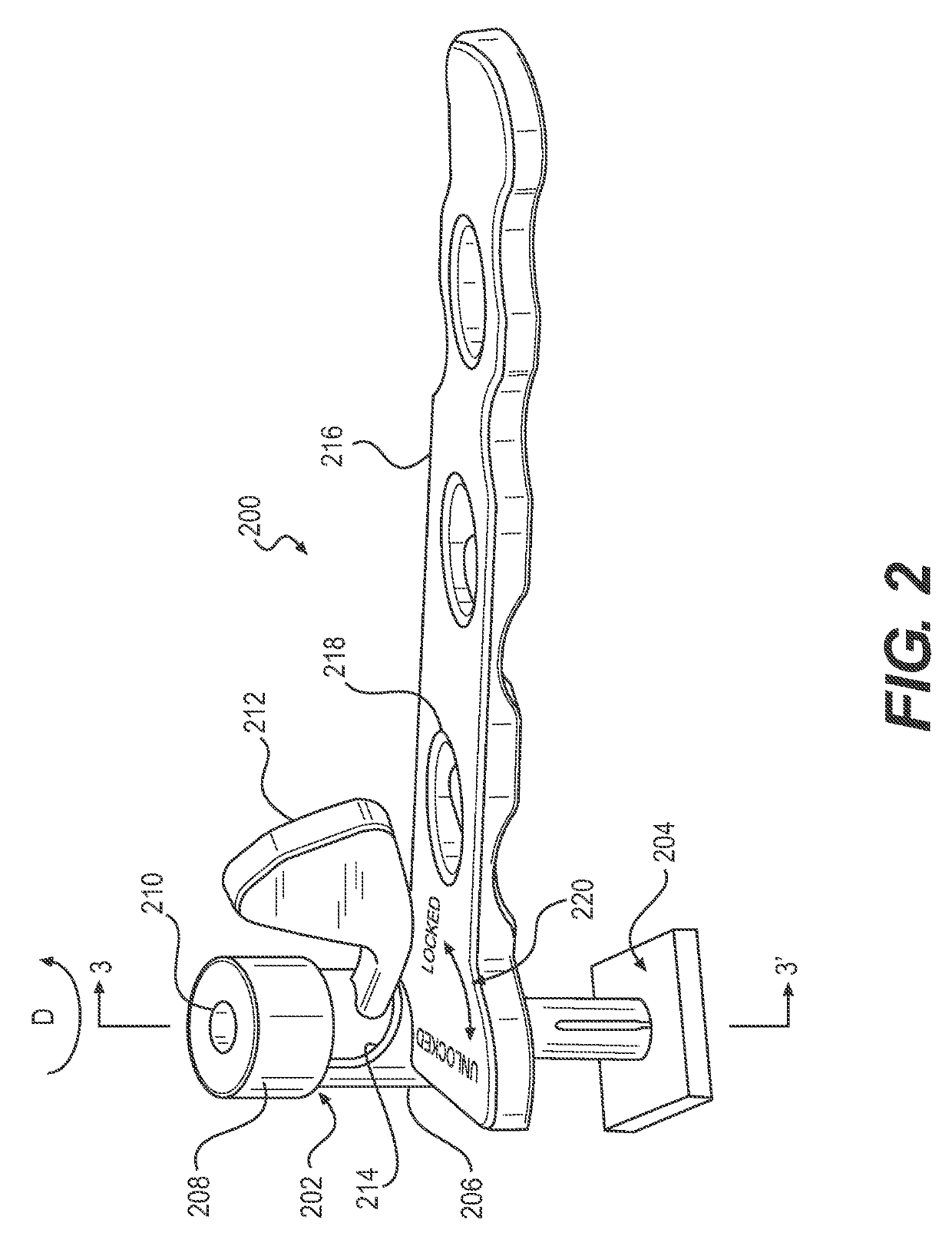
[0017]Embodiments of the disclosure are generally directed to devices, systems, and methods for aligning and locking a drill guide into a polyaxial hole while maintaining the form and function of the polyaxial hole. Specifically, embodiments are directed to a drill guide configured to align a drill bit with a nominal axis / trajectory of a polyaxial screw hole. The inventive drill guide may be used with bone plates with locking and / or non-locking fasteners for dynamic compression of the bone. The hole designs may allow for polyaxial locking of the fasteners. The inventive drill guide advantageously provides for one-handed operation with quick and reliable locking capabilities. The inventive drill guide is also ergonomic and its design is streamlined.

[0018]The plates may be adapted to contact one or more of a femur, a distal tibia, a proximal tibia, a proximal humerus, a distal humerus, a clavicle, a fibula, an ulna, a radius, bones of the foot, bones of the hand, or other suitable bon...


PUM


Abstract

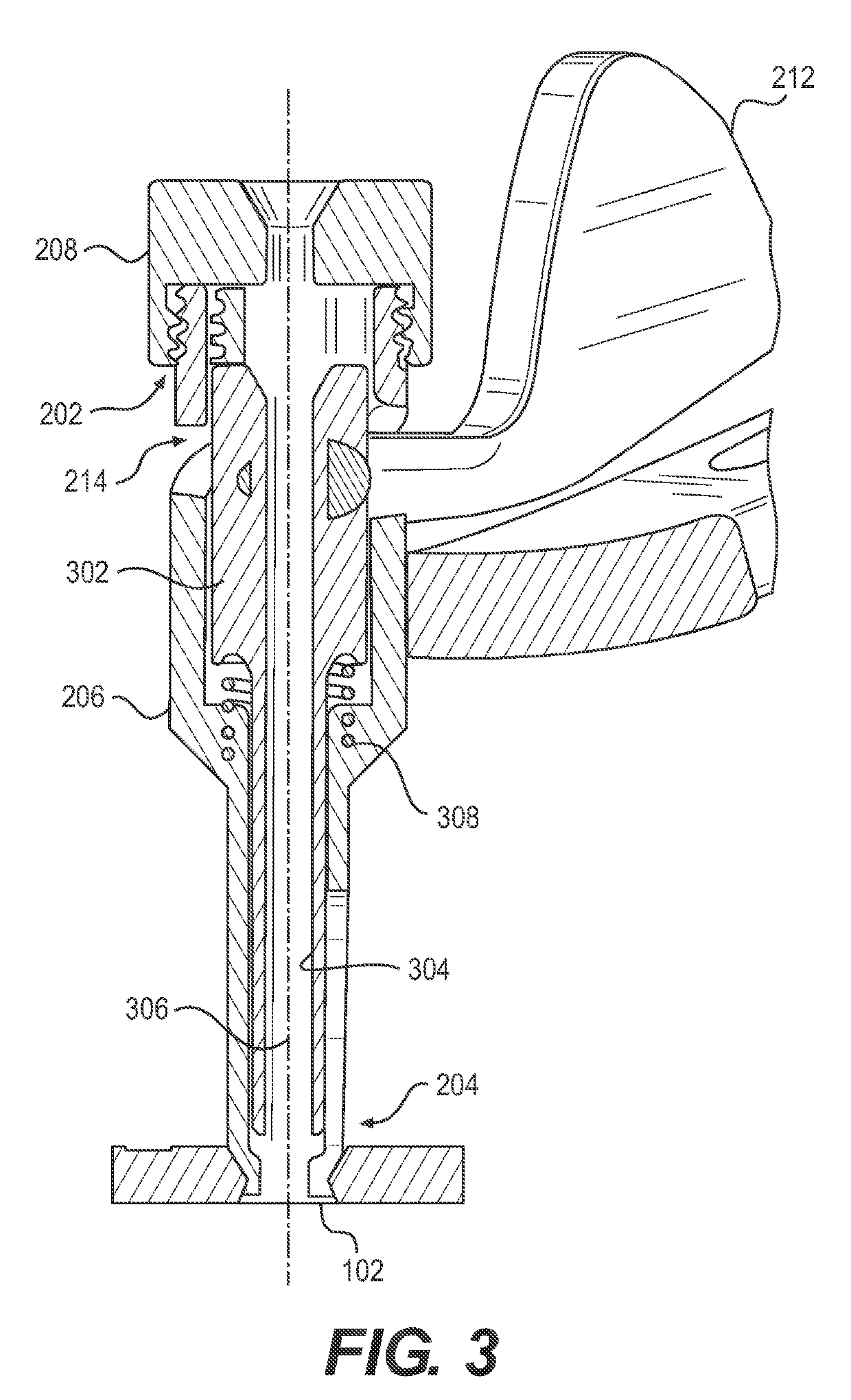
Devices, systems, and methods for locking a drill guide into a polyaxial hole while maintaining the form and function of the polyaxial hole are provided herein. In some embodiments, the drill guide includes a hollow outer body extending from a proximal end to a distal end and having a slot disposed proximate the proximate end, wherein the distal end is configured as a reverse collet having a plurality of prongs; an inner body having a central channel extending therethrough; and a lever coupled to the inner body through the slot, wherein the slot is shaped such that rotation of the lever results in motion along a central axis of the drill guide, and wherein a distal end of the inner body is configured to prevent radially inward deflection of the plurality of prongs when the inner body is in a lowermost position.

Description

RELATED APPLICATIONS[0001]This application claims priority to U.S. Provisional Patent Application No. 62 / 655,934, filed Apr. 11, 2018, the contents of which are hereby incorporated by reference in its entirety.FIELD[0002]The present disclosure relates to surgical devices, and more particularly, stabilization systems, for example, for trauma applications.BACKGROUND[0003]Bone fractures are often repaired by internal fixation of the bone, such as diaphyseal bone, using one or more plates. The plate is held against the fractured bone with screws, for example, which engage the bone and heads which provide a compressive force against the plate. The plate and bone are thus forced against each other in a manner that transfers load primarily between a bone contacting surface of the plate and the bone surface to reinforce the fractured bone during healing. This manner of plating generally creates relatively low stress concentration in the bone, as there may be a large contact area between the...

Claims


Application Information

Patent Timeline
IPC IPC(8): A61B17/17
CPCA61B2017/00477A61B17/17A61B17/1728A61B17/808A61B17/8872
Inventor LAIRD, JR., DAVIDZINGALIS, GABRIELLEDAVISON, ANDREW
Owner GLOBUS MEDICAL INC
Learn More