Liquid Displacement Devices

a technology for liquid displacement and devices, applied in aquatic toys, applications, domestic applications, etc., can solve the problems of lack of flexibility in application, unfavorable user comfort, and no novelty device, such as toys, can be provided

Inactive Publication Date: 2013-03-14
ROBERTSON TIM
View PDF0 Cites 6 Cited by
  • Summary
  • Abstract
  • Description
  • Claims
  • Application Information

AI Technical Summary

Benefits of technology

The patent describes a device that helps save water and energy in baths or pools by reducing the amount of water needed. It is designed to be attached to a container and resides beneath the surface of the water. The device can have passive or active features, such as lights, sounds, or a suction cup for attaching toys. The device also has one or more orifices that allow it to be placed on different surfaces and in different positions. Overall, this device provides engagement, entertainment, and challenge for children and users, making it a better toy or bath experience.

Problems solved by technology

Such devices are uncomfortable for the user, and often lack flexibility of application.
Whilst some of the aforementioned devices are intended for use in a bath, such as for example the device depicted in DE-U1-202008006188, none shows the provision of a novelty device, such as a toy, that is intended to displace large volumes of liquid and are suitable for stowage as well as well as providing a degree of entertainment to bathers.

Method used


Image

  • Liquid Displacement Devices
  • Liquid Displacement Devices
  • Liquid Displacement Devices

Examples


first embodiment

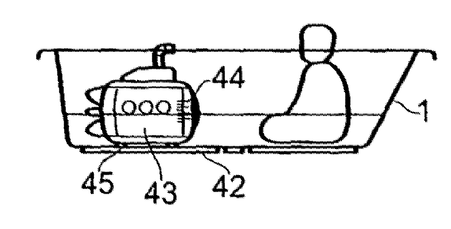
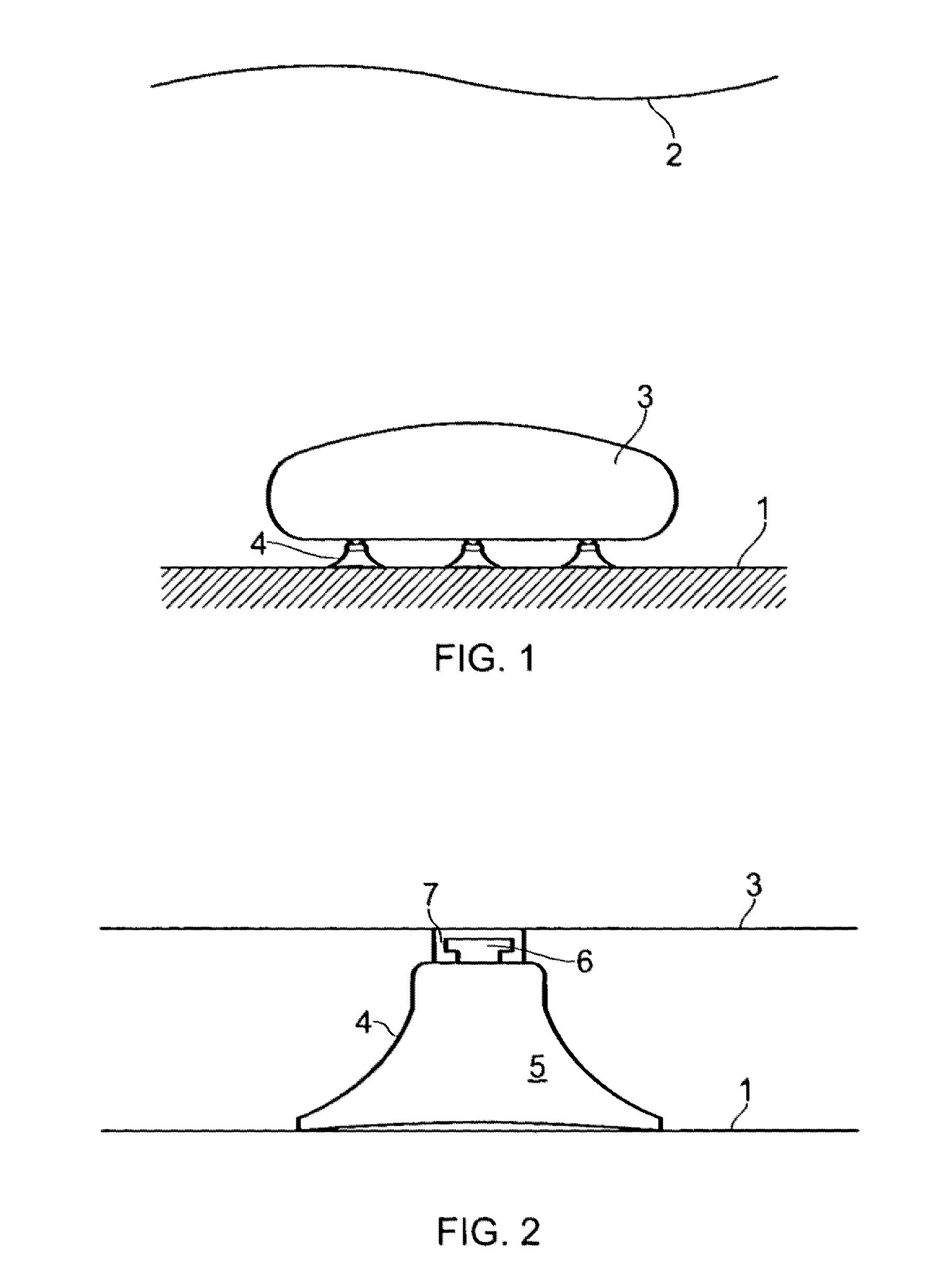
[0083]Referring now to FIG. 1, a water storage vessel 1 contains a volume of water to a level as illustrated at 2. There is shown introduced into the water storage vessel a water displacement device in post-inflated condition 3 comprising a generally rectilinear block of a material which after inflation expands to a larger volume.

[0084]The device 3 is attached to the inside of the vessel by suction cups 4 so that the inflated device lies affixed to a side of the water storage vessel submerged beneath the surface of the water, thereby displacing the volume of water equivalent entirely or in part to the volume of air contained therein. In this example, the water displacement device 3 is attached to the floor or base of the water storage vessel 1; this attachment is generally done by hand with pushing of the device by hand providing enough force to temporarily fix the device to the vessel surface.

[0085]Referring now to FIG. 2, the suction cup 4 is shown permanently attached to the wate...

second embodiment

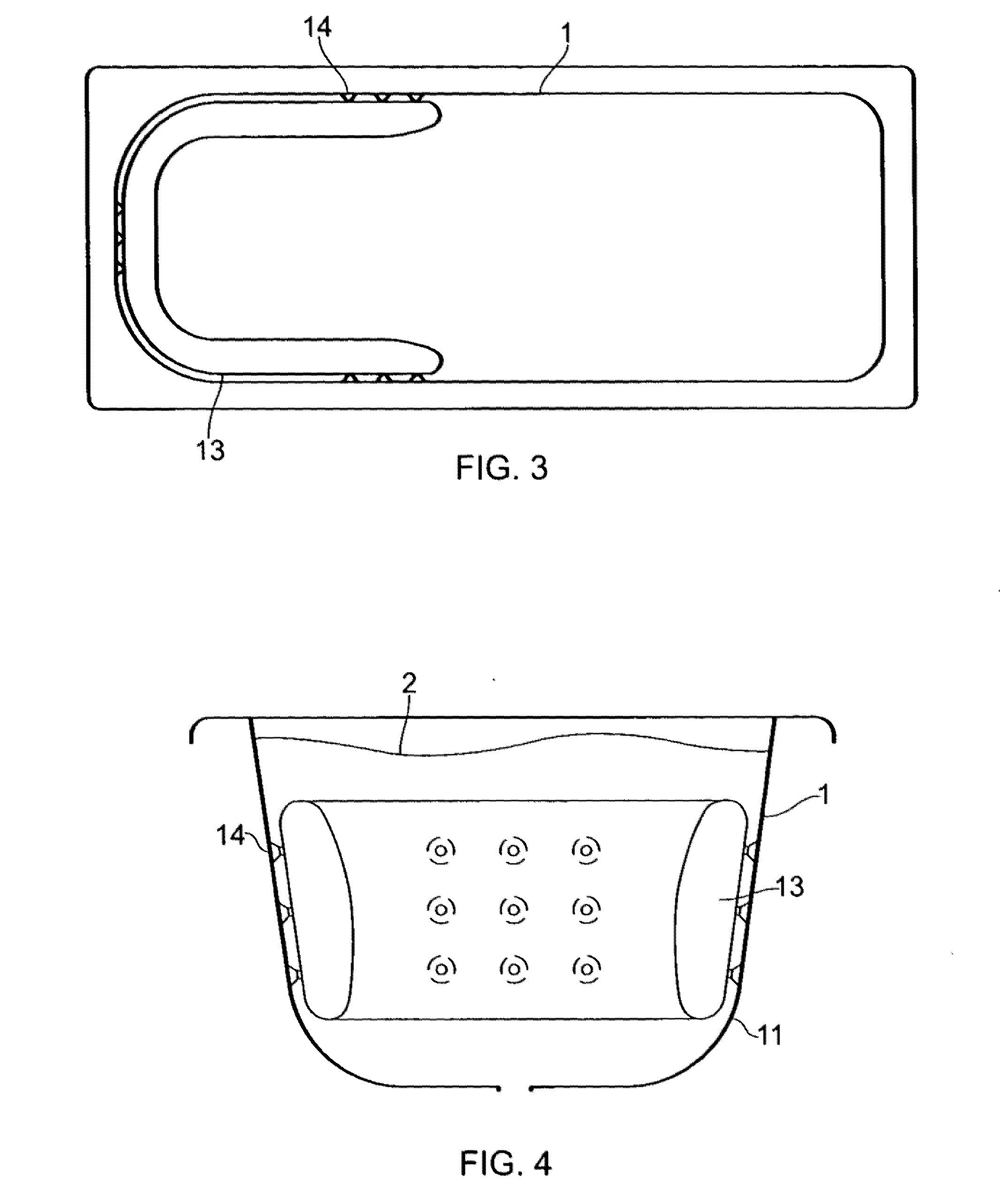
[0086]FIGS. 3 and 4 show an alternative second embodiment, in plan view, and cross section respectively. In this example, the water displacement device 13 is attached to the wall 11 of the water storage vessel 1 using suction cups 14. The device 13 forms a u-shaped cushion around the wall 11 of the water storage vessel 1 against which a user can lie as it forms a cushion like structure.

third embodiment

[0087]FIGS. 5 and 6 show plan and cross sectional views respectively of a further alternative third embodiment in which the water displacement device 23 comprises five separated inflated compartments, connected such that air can flow between them to form one continuous device. Alternatively, these compartments may be separated physically but attached to form one device. The device, in use is placed starting at the top of an end 25 of the wall 21 and flowing down the wall 21 onto the base 22 of the water storage device 1. This forms, in effect a full or near to full length body pillow for a person lying down in the bath.

[0088]The first compartment 23a is preferably shaped as a roll and can be used as a neck support by a bather. The other compartments are essentially square or rectangular in shape. Although every compartment can be attached to the vessel 1 using suction cups 24, this is not required and for normal use only two or three compartments need the suction cups 24 to retain t...


PUM


Abstract

A liquid displacement device (3,13,23,33,43,53,63,73) comprises one or multiple inflatable containers (3,13,23,233,338,336,43,53,63,66,67,73,74), and an attachment (4,14,24,34,45,55,65,66,75) for attaching the liquid displacement device to a liquid storage vessel (1) wherein, when inflated and attached to an inner surface (11) of the liquid storage vessel (1), the liquid displacement device displaces liquid in the liquid storage vessel. The one or more containers (3, 13,23,23a,33a,33b,43,53, 63,66,67,73,74) may reside entirely or partially below the surface (2) of the liquid within the liquid storage vessel (1). The attachment comprises a tether (66) or suction means (4,14,24,34,45,55,65,75) such as suction cups. The container comprises a single compartment (3,13,53,63), or multiple compartments (23,23a, 33a, 33b,43,66,67,73,74) connected such that gas can flow between them. The device may be a toy including a storage compartment (35,50,68).

Description

FIELD OF THE INVENTION[0001]This invention relates to a device for displacement of liquid, particularly water in a storage vessel such as a bath or pool.BACKGROUND OF THE INVENTION[0002]As fuel costs increase and in light of the growing concerns about carbon dioxide emissions and global warming, considerable emphasis is being placed on saving water, and the energy used to heat water for baths and swimming polls, in residential, commercial and educational premises. A modern bath can hold in excess of 150 litres of water, about three times as much water as is used during a single shower.[0003]Increasingly water authorities, suppliers and industry bodies are actively encouraging consumers to take showers rather than baths. However, there remain a significant number of people who bathe, whether through choice or not.[0004]There are several ways to use less water within a water storage vessel, such as a bath or pool. One way is to manufacture a shallower bath; however this is not a viabl...

Claims


Application Information

Patent Timeline
IPC IPC(8): E04H4/14A47K3/00
CPCA47K3/001A47K3/125E04H4/14E04H4/0025A63H23/10
Inventor ROBERTSON, TIM
Owner ROBERTSON TIM
Why Eureka
Try Eureka