
Method and apparatus to monitor a reservoir or a structure

a technology for reservoirs and structures, applied in the field of load cells, can solve the problems of important profit loss, silo emptying, and uninterrupted supply of animals' food,

Active Publication Date: 2019-09-26
TECH INTELIA INC
View PDF0 Cites 2 Cited by
  • Summary
  • Abstract
  • Description
  • Claims
  • Application Information

AI Technical Summary

Benefits of technology

The invention is a system for safely installing and monitoring the weight of a reservoir (like a silo) without disconnecting any feed supply lines. The system uses a lifting device that connects to the reservoir and a support member on the ground to induce a movement and lift the reservoir's legs. The installation procedure is minimized, and a permanent lifting device is used for better stability in windy weather. The load cell is connected to both the lifting device and the support member, improving accuracy in monitoring the weight of the reservoir.

Problems solved by technology

Many facilities, such as cattle farms, must provide the animals an uninterrupted supply of food.
However, it occurs that the silo gets empty without the producer or the feed supplier is notified.
If not resolved quickly, this situation may cause important profit loss.
The suspension point of such assembly requires to raised several inches from the ground and requires a beefy and large A-Frame.
Such frame Inconvenient of such frame includes that the system has a very large footprint and becomes unusable when the bin is mounted on small concrete block.
Also, the size and the weight of this assembly render difficult the manipulation of the heavy parts and require an important men effort during installation.
Also, the system disclosed in U.S. Pat. No. 7,980,129 requires a connector arranged to be connectable to one of the bin legs and supporting the load, which increases the complexity and costs of installation.
Another problem frequently found, several weighing equipment for feeding and weighing animals are mounted on load cells.
When a load cell fails, the replacement is often complex and requires lifting equipment which complicate the intervention.

Method used


Image

  • Method and apparatus to monitor a reservoir or a structure
  • Method and apparatus to monitor a reservoir or a structure
  • Method and apparatus to monitor a reservoir or a structure

Examples


Embodiment Construction

[0061]A novel method and apparatus to monitor the material weight contained or weight of a reservoir, a tank, a silo or any other types of structures will be described hereinafter. Although the invention is described in terms of specific illustrative embodiment, it is to be understood that the embodiment described herein are by way of example only and that the scope of the invention is not intended to be limited thereby.

[0062]In some embodiments, the method and apparatus may be provided to monitor the material weight contained in a silo tank. The material could be liquid or solid or a mixed of liquid and solid.

[0063]In this document, the present invention is presented as a device for monitoring a reservoir or a silo. One skilled in the art shall understand that the present device and method may be adapted to monitor, weight and / or lift other structures without departing from the principles of the present invention. As examples, the structures may be a system for weighting animals or...


PUM


Abstract

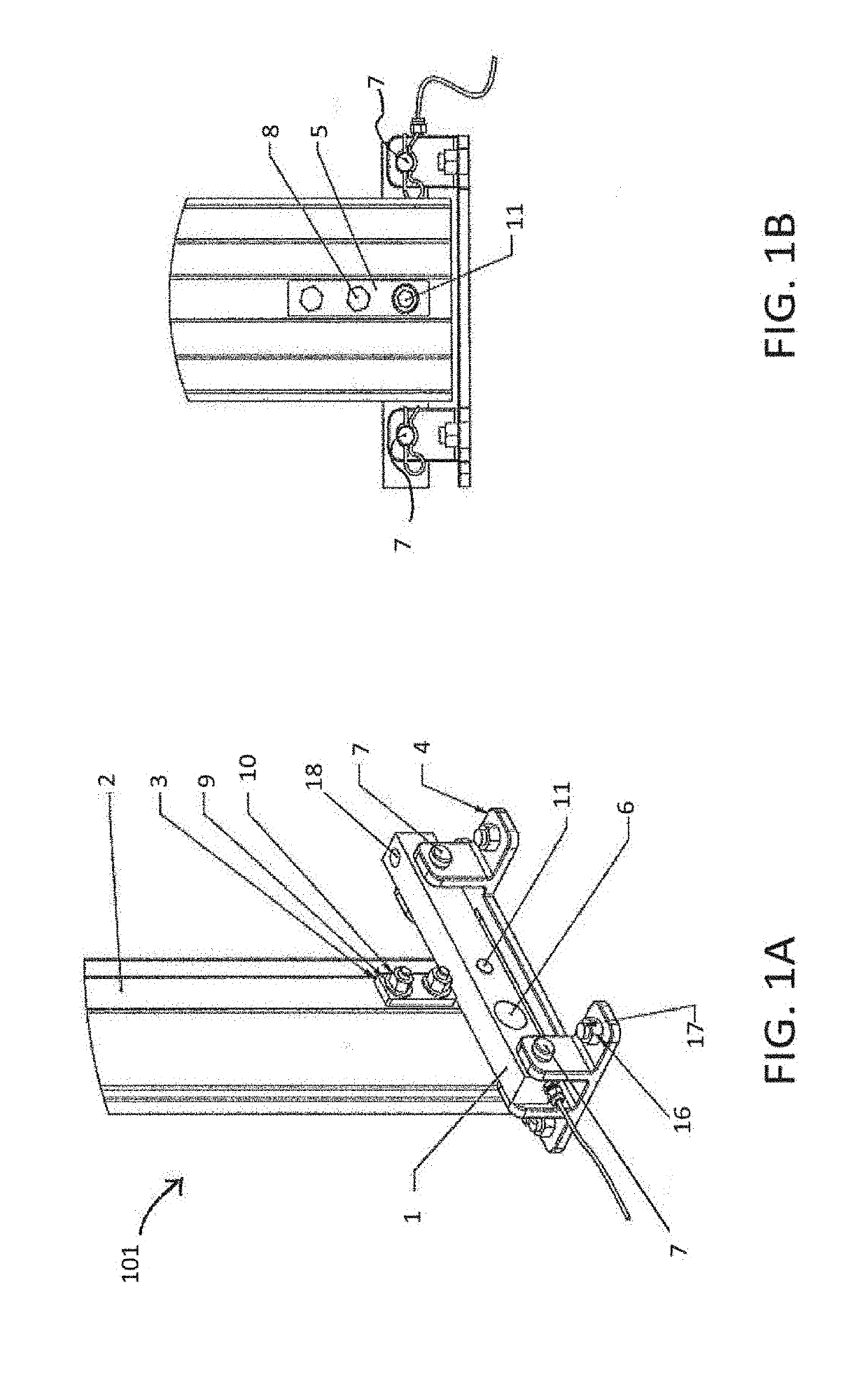
A method and apparatus to monitor the weight of a silo or tank is disclosed. The system is adapted to be attached to a leg of the silo and comprises a load cell, a support member anchored to the ground and a lifting device attached to the load cell and to the support member. The load cell comprises two extremities that are attached to the silo leg and comprises an aperture there between. The aperture is preferably threaded to receive the lifting device, such as a bolt. The bolt is rotated using a tool as to induce a movement of the load cell along the axis of the bolt thereby lifting the load cell and the attached silo leg. Strain gauges are attached to the load cell to measure the variation in an electric or optical signal that is translated in human readable data using a monitoring device.

Description

CROSS-REFERENCE TO RELATED APPLICATIONS[0001]The present patent application claims the benefits of priority of U.S. Provisional Patent Application No. 62 / 380,556, entitled “METHOD AND APPARATUS TO MONITOR A RESERVOIR OR A STRUCTURE” and filed at the United States Patent and Trademark Office on Aug. 29, 2016, the content of which is incorporated herein by reference. The present patent application is also a continuation of the PCT patent application no. PCT / CA2017 / 051015, entitled “METHOD AND APPARATUS TO MONITOR A RESERVOIR OR A STRUCTURE” filed at the World Intellectual Property Organization on Aug. 29, 2017, the content of which is also incorporated herein by reference.FIELD OF THE INVENTION[0002]The present invention generally relates to the field of load cells, and more particularly to devices and methods for weighting and lifting reservoir, tank, silo or other types of structures.BACKGROUND OF THE INVENTION[0003]Many facilities, such as cattle farms, must provide the animals an ...

Claims


Application Information

Patent Timeline
IPC IPC(8): G01G21/23G01G19/52
CPCE04H7/22G01G19/52G01G21/23G01G13/024G01G23/02
Inventor BOUCHARD, CLAUDE
Owner TECH INTELIA INC
Learn More