Variable gain amplifier

Active Publication Date: 2019-09-12
BAE SYST INFORMATION & ELECTRONICS SYST INTERGRATION INC
View PDF0 Cites 1 Cited by
  • Summary
  • Abstract
  • Description
  • Claims
  • Application Information

AI Technical Summary

Benefits of technology

The present disclosure provides an improved variable gain amplifier that can adjust its gain without affecting input impedance, output impedance, noise figure, and third-order output intercept point. The amplifier circuit includes a first amplifier, a second amplifier, and a variable capacitor connected between them. The variable capacitor can be switched on or off to adjust the gain of the amplifier circuit. Additionally, the amplifier circuit may also include a shunt peaking inductor to reject common mode signals. The technical effects of the patent text are to provide a more robust and versatile variable gain amplifier that can be used in various applications.

Problems solved by technology

However, one drawback associated with this variable gain amplifier 200 is that as the gain decreases, the third-order output intercept point (OIP3) decreases as shown in FIG. 2B, which is a graph of linear gain variation in dB and linear OIP3 variation in decibel-milliwatts (dBm) versus control voltage variation.
In some instances, a multistage amplifier may be vulnerable to oscillation or lack of stability.

Method used


Image

  • Variable gain amplifier
  • Variable gain amplifier
  • Variable gain amplifier

Examples


Embodiment Construction

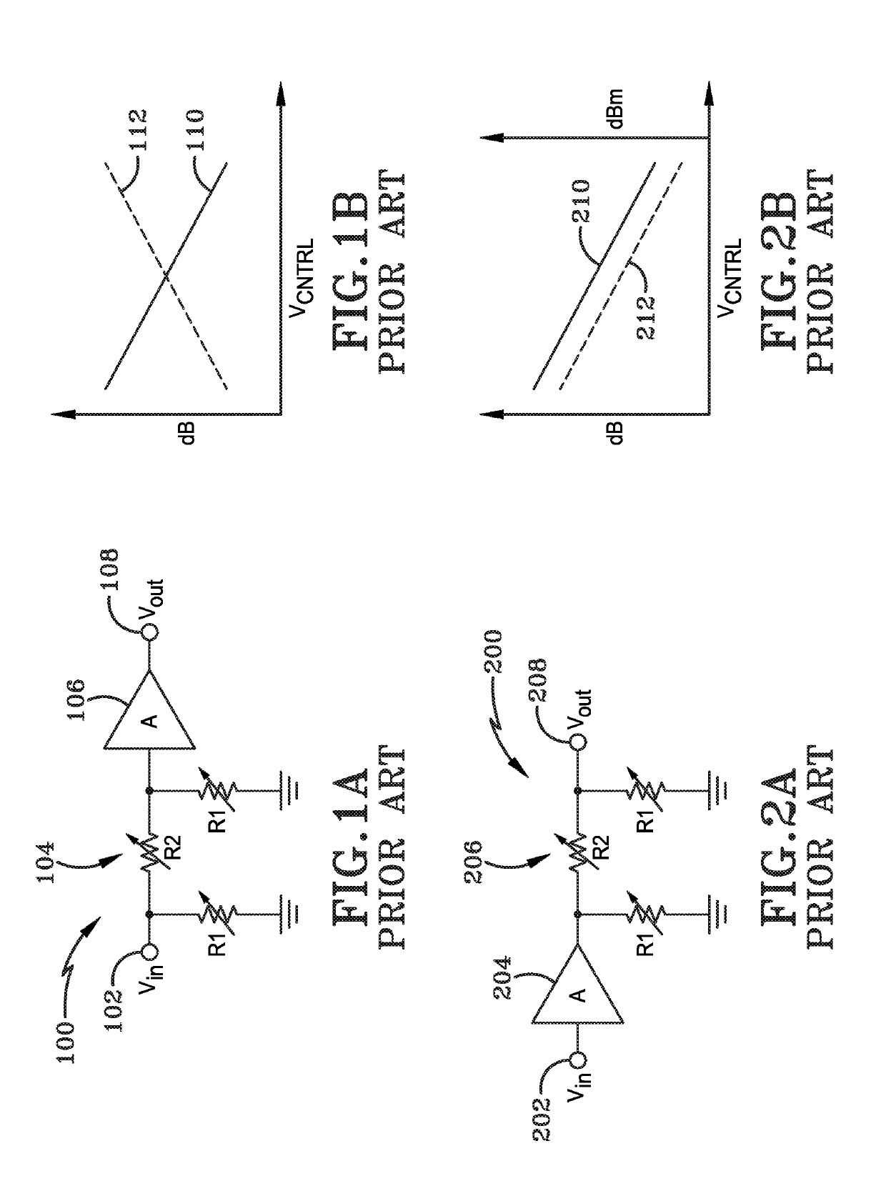
[0037]FIG. 1A illustrates a schematic view of a PRIOR ART variable gain amplifier 100 which includes an input port 102, a voltage variable attenuator 104, an amplifier 106 and an output port 108. The voltage variable attenuator 104 is a pi type voltage variable attenuator.

[0038]The input port 102 is connected to the voltage variable attenuator 104, the voltage variable attenuator 104 is connected to the amplifier 106, and the amplifier 106 is connected to the outport port 108.

[0039]The operation of the PRIOR ART variable gain amplifier 100 is well known, and, for brevity purposes, will not be fully discussed herein; however, a brief description of the operation and one shortcoming of the PRIOR ART variable gain amplifier 100 will be discussed below.

[0040]In operation, a radio frequency (RF) signal (not shown) enters the input port 102 and the voltage variable attenuator 104 attenuates the RF signal producing an attenuated RF signal. The attenuated RF signal enters the amplifier 106 ...


PUM


Abstract

A variable gain amplifier circuit including a first amplifier, a second amplifier, and a variable capacitor connected in series between the first amplifier and the second amplifier is disclosed. As a gain of the variable gain amplifier circuit varies, the input impedance, output impedance, noise figure and third-order output intercept point (OIP3) of the variable gain amplifier circuit remain unchanged.

Description

STATEMENT OF GOVERNMENT INTEREST[0001]This present disclosure was made with United States Government support under Contract No. FA8650-17-C-7709 awarded by U.S. Dept. of the Air Force. The United States Government has certain rights in this disclosure.BACKGROUNDTechnical Field[0002]The present disclosure relates to systems and methods for communication systems. More particularly, the present disclosure relates to radio frequency (RF) variable gain amplifiers. Specifically, the present disclosure relates to variable gain amplifiers having a variable gain that does not affect an input impedance, an output impedance, a noise figure and a third-order output intercept point (OIP3) of the variable gain amplifier circuit as the gain varies.BACKGROUND INFORMATION[0003]Generally, radio frequency (RF) is any frequency within the electromagnetic spectrum associated with radio wave propagation. Typically, applying an RF current to an antenna creates an electromagnetic field that is able to prop...

Claims


Application Information

Patent Timeline
IPC IPC(8): H03F7/04H03F1/26H03F1/34
CPCH03F7/04H03F1/34H03F1/26H03F3/189H03F3/191H03F3/3435H03F2200/211H03F2200/408H03F2200/451H03G1/0088H03G1/0094
Inventor KRISHNAMURTHI, KATHIRAVANFLEWELLING, GREGORY M.
Owner BAE SYST INFORMATION & ELECTRONICS SYST INTERGRATION INC
Why Eureka
Try Eureka