Apparatus and method for electronic lock key indicator

Inactive Publication Date: 2011-05-05
WEINSTEIN HILLEL
View PDF5 Cites 22 Cited by
  • Summary
  • Abstract
  • Description
  • Claims
  • Application Information

AI Technical Summary

Benefits of technology

[0005]The present invention introduces an electronic device and system, included within a housing that can be attached to most of the known keys, providing an indication of the most recent status of the lock corresponding to said key. Said device shall indicate whether the lock was left locked or unlocked. According to the teachings of this invention, when the user inserts the key into the lock and rotates the key about its longitudinal axis in a clockwise (CW) or counterclockwise (CCW) direction, which rotation causes the lock to correspondingly unlock or lock, the attached device shall sense the direction of rotation of the key, thus indicating whether the lock was left in an unlocked or locked position. Sensing of the direction of rotation of the key is achieved independently of the user's positioning of his fingers and/or hand, and does not depend on users' fingers pressure during the rotation of the key and the attached device. Moreover, there is no need to use magnets and/or mechanical devices. In other words, the particular manner which caused the rotation of the key and the particular positioning of the user's thumb and/or fingers on the attached housing of this invention are substantially inconsequential insofar as the core of this invention is concerned. According to the teachings of this invention, the indication of the direction of rotation of the key is achieved by means of electronic sensing using transducers that issue electronic signals the detection of which uniquely indicates a clockwise (CW) or counter

Problems solved by technology

However, following his departure, he or she may be unable to recall whether or not they have actually locked the door, securing it by turning the corresponding key into a locked position.
Many keys are inserted into the lock in a horizontal position i.e. the key head is parallel to the floor, such that a thumb-activated switch may be difficult to achieve.
Furthermore, occasional contact of keys including said attachments with various external objects, e.g.—coins or other objects in a user pockets, may reset the memory / indicator into an erroneous position.
Moreover, several users may have different physiological structures of hands and fingers resulting in a great variety of forces being applied to the key while rotated inside the lock, which may lead to errors in the indicator output.

Method used


Image

  • Apparatus and method for electronic lock key indicator
  • Apparatus and method for electronic lock key indicator
  • Apparatus and method for electronic lock key indicator

Examples


Embodiment Construction

[0039]All technical terms used herein have the same meaning as commonly understood by one skilled in the art pertaining to the invention and in the art of electronics.

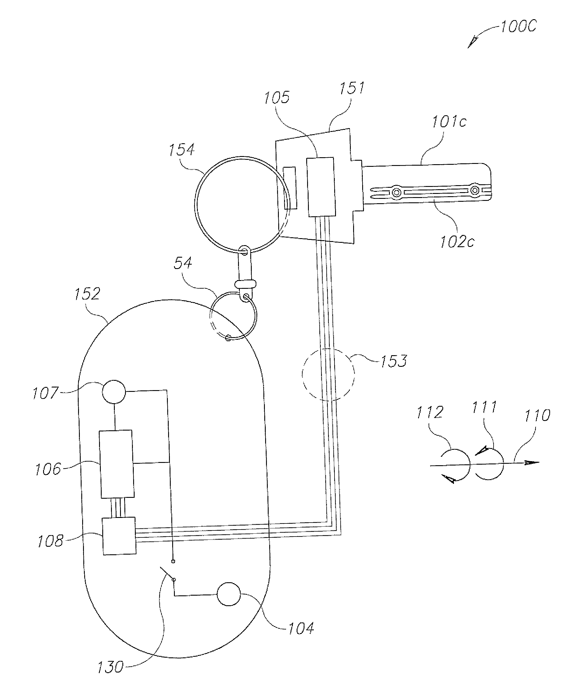
[0040]The disclosed subject matter is described below with reference to flowchart illustrations and / or block diagrams of methods, apparatus (systems) and computer program products according to embodiments of the subject matter. It will be understood that each block of the flowchart illustrations and / or block diagrams, and combinations of blocks in the flowchart illustrations and / or block diagrams, can be implemented by computer program instructions. These computer program instructions may be provided to a processor of a general purpose computer, special purpose computer, digital controller, or other programmable data processing apparatus to produce a machine, such that the instructions, which execute via the processor of the computer or other programmable data processing apparatus, create means for implementing the fun...


PUM


Abstract

An apparatus for tracking and indicating the status of a lock, comprising: a movement sensing device for sensing movement of a key related to said lock and providing information about said movement; a controller for reception of said information about said movement, processing said information and identifying a key rotation event that is associated with a lock status; and an indication unit being connected to said controller; providing an indication of the lock status according to control signals that are provided by said controller.

Description

RELATED APPLICATIONS[0001]This application claims priority from provisional patent applications serial number U.S. 61 / 279,969 filed on Oct. 29, 2009 tilted Electronic Lock Indicator, and serial number U.S. 61 / 335,202 filed on Jan. 4, 2010 tilted Electronic Lock Key Indicator the disclosures of which are incorporated herein by reference.BACKGROUND[0002]The present invention relates to tracking the status of a lock in general, and to providing an indication of the status of a lock being either locked or unlocked, in particular.[0003]Quite often, people forget whether they have locked the door in the house, office, or other premises, or not. As a common occurrence—someone may depart a building intending to secure it by externally locking a certain door using its corresponding key, upon departure. However, following his departure, he or she may be unable to recall whether or not they have actually locked the door, securing it by turning the corresponding key into a locked position. Henc...

Claims


Application Information

Patent Timeline
IPC IPC(8): E05B41/00
CPCE05B19/22Y10T70/8189Y10T70/8027Y10T70/70
Inventor WEINSTEIN, HILLEL
Owner WEINSTEIN HILLEL
Why Eureka
Try Eureka