
Estimation of temperature states for an electric water heater from inferred resistance measurement

a technology of inferred resistance and temperature state, which is applied in the direction of lighting and heating equipment, process and machine control, instruments, etc., can solve the problems of increasing the complexity and cost of residential electric storage water heaters, the inability to accurately predict the temperature state of electric water heaters, and the failure of the tank itsel

Active Publication Date: 2019-09-12
BATTELLE MEMORIAL INST
View PDF0 Cites 4 Cited by
  • Summary
  • Abstract
  • Description
  • Claims
  • Application Information

AI Technical Summary

Benefits of technology

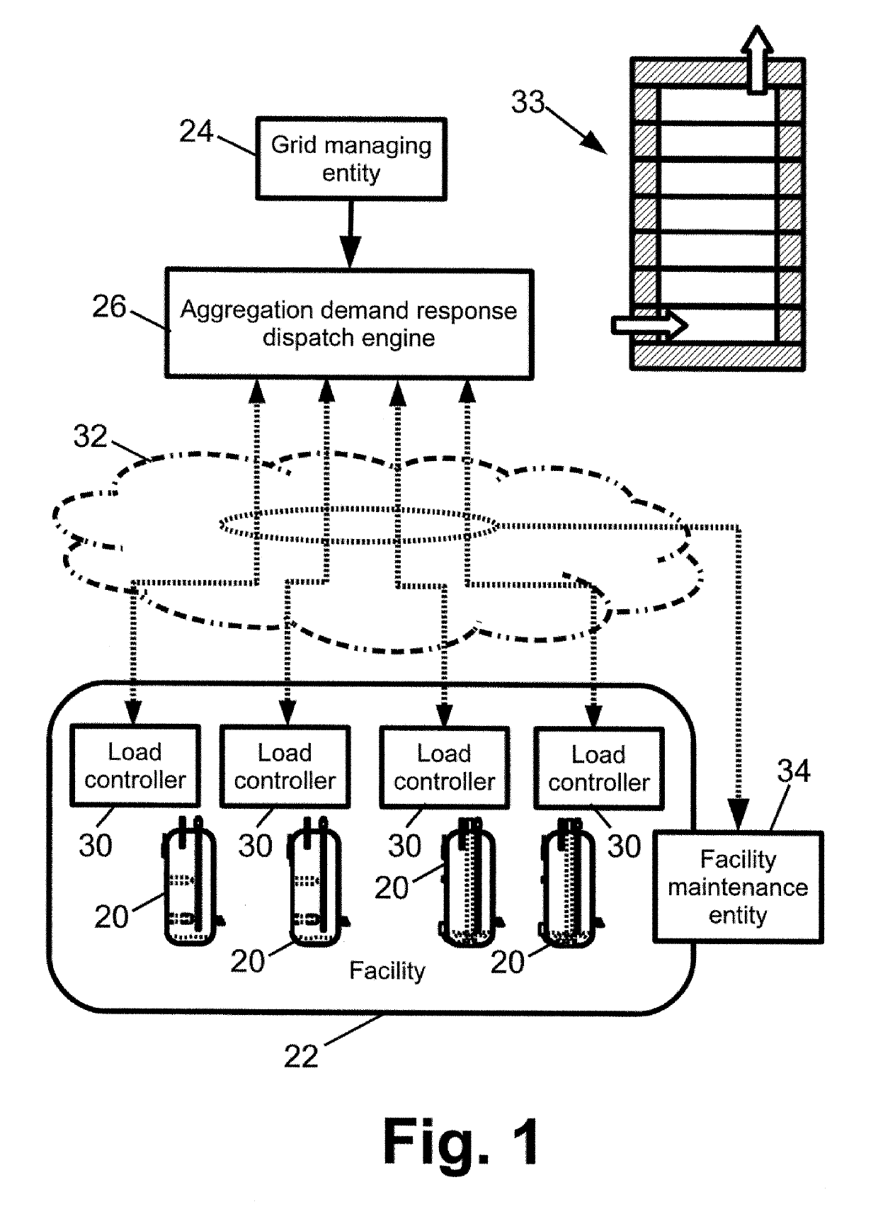
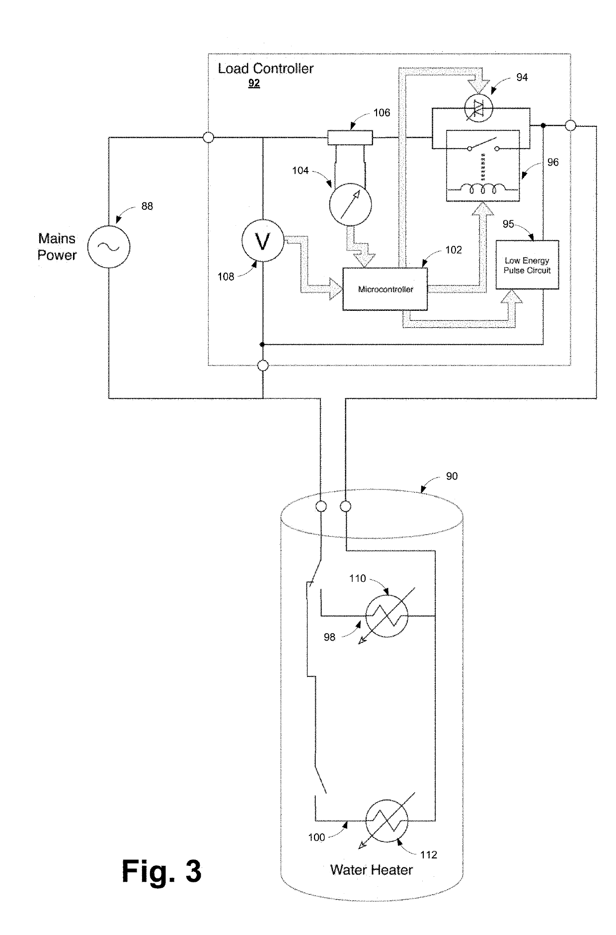
The patent describes a system for controlling a water heater and its components. The system includes a load controller for controlling the water heater, an aggregation demand response dispatch engine for sending demand response commands to the load controller, and a condition-based maintenance system for detecting failure modes in the water heater and / or its electrical load. The load controller receives information from the water heater through a resistance reading of the heating elements, as well as power input to the water heater and the electrical load. The condition-based maintenance system analyzes the temperature readings and power input to detect any failure modes in the water heater and electrical load, providing early detection and preventive maintenance. Overall, the system improves the efficiency and reliability of water heating and electrical load management.

Problems solved by technology

To maintain the integrity of the tank, specialized sensors must be used, increasing the complexity and the cost of residential electric storage water heaters.
Thus, the parts and labor required to install external temperature probes are expensive, and create potential failure points of the tanks themselves.

Method used


Image

  • Estimation of temperature states for an electric water heater from inferred resistance measurement
  • Estimation of temperature states for an electric water heater from inferred resistance measurement
  • Estimation of temperature states for an electric water heater from inferred resistance measurement

Examples


Embodiment Construction

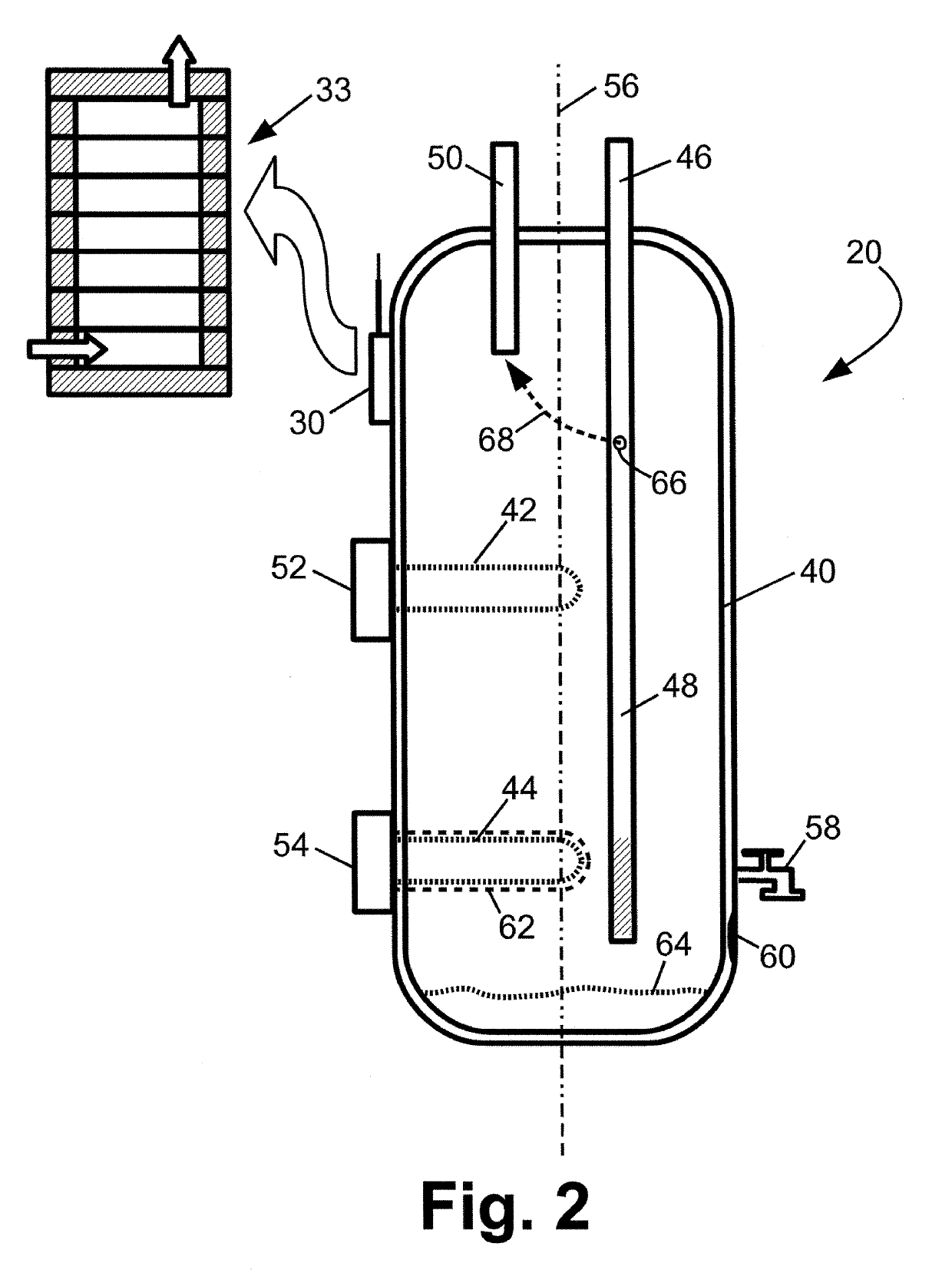
[0018]A more complete understanding of the components, processes and apparatuses disclosed herein can be obtained by reference to the accompanying drawings. These figures are merely schematic representations based on convenience and the ease of demonstrating the present disclosure, and are, therefore, not intended to indicate relative size and dimensions of the devices or components thereof and / or to define or limit the scope of the exemplary embodiments.

[0019]Although specific terms are used in the following description for the sake of clarity, these terms are intended to refer only to the particular structure of the embodiments selected for illustration in the drawings, and are not intended to define or limit the scope of the disclosure. In the drawings and the following description below, it is to be understood that like numeric designations refer to components of like function.

[0020]The singular forms “a,”“an,” and “the” include plural referents unless the context clearly dictat...


PUM


Abstract

A water heater that includes a cylindrical storage tank and at least one heating element, is modeled using a one-dimensional model that includes: a vertical stack of disks representing the water volume in the cylindrical storage tank, and a stack of annular segments surrounding the vertical stack of disks. Various temperature measurements are determined via resistance calculations of the at least one heating element. The stack of annular segments represents the cylindrical wall of the cylindrical storage tank. The one-dimensional model may be used by a condition-based maintenance system comprising an electronic data processing device configured to detect a failure mode present in the water heater based on an output of the water heating model component. Some illustrative failure modes include insulation disturbance, heating element failure, excessive sediment buildup, or a drip tube rupture.

Description

[0001]This application is a continuation-in-part of U.S. patent application Ser. No. 14 / 976,602, filed Dec. 21, 2015 and titled “ESTIMATION OF UNKNOWN STATES FOR AN ELECTRIC WATER HEATER WITH THERMAL STRATIFICATION AND USE OF SAME IN DEMAND RESPONSE AND CONDITION-BASED MAINTENANCE”, which claims the benefit of U.S. Provisional Application No. 62 / 095,593 filed Dec. 22, 2014 and titled “ESTIMATION OF UNKNOWN STATES FOR AN ELECTRIC WATER HEATER WITH THERMAL STRATIFICATION AND USE OF SAME IN DEMAND RESPONSE AND CONDITION-BASED MAINTENANCE”. U.S. patent application Ser. No. 14 / 976,602 filed Dec. 21, 2015 and Provisional Application No. 62 / 095,593 filed Dec. 22, 2014 are incorporated herein by reference in their entirety.BACKGROUND[0002]The following relates to the water heater arts, water heater control arts, water heater maintenance arts, and related arts.[0003]Water heaters are ubiquitous appliances in residential and commercial settings, used to provide hot water for washing, cleaning...

Claims


Application Information

Patent Timeline
IPC IPC(8): F24H9/20G05B17/02
CPCG05B17/02F24H2250/02F24H9/2021F24H15/176F24H15/281F24H15/288F24H15/104F24H15/20F24H15/174F24H15/225F24H15/168F24H15/254F24H15/45F24H15/12F24H15/124F24H15/37F24H15/407F24H15/144
Inventor MCCULLOUGH, JASON J.JONES, MICHAEL A.REHBERG, ERIC L.
Owner BATTELLE MEMORIAL INST
Learn More