Variable magnification optical system and imaging apparatus
- Summary
- Abstract
- Description
- Claims
- Application Information
AI Technical Summary
Benefits of technology
Problems solved by technology
Method used
Image

Examples
example 1
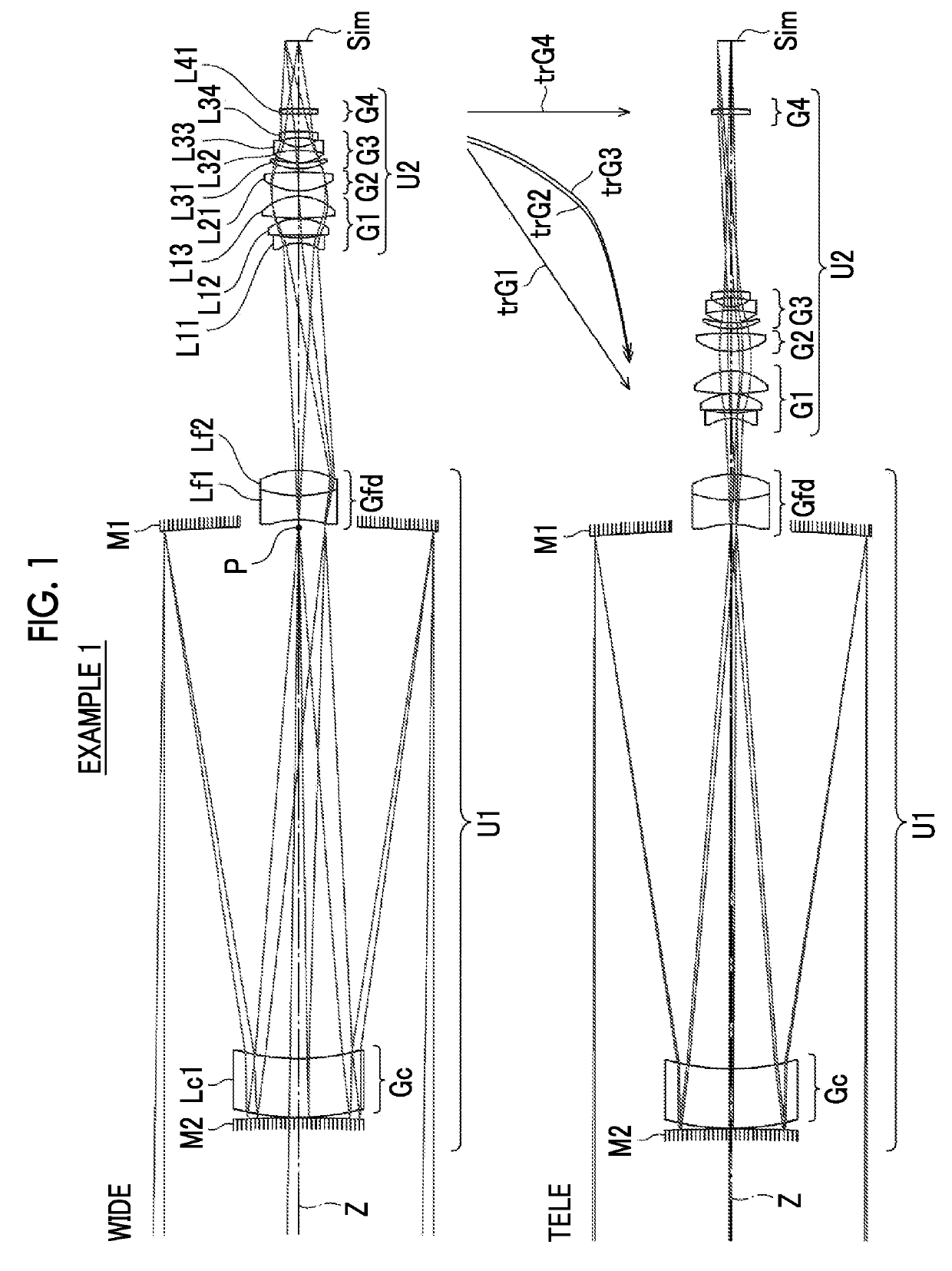
[0093]A cross-sectional view and an optical path of a variable magnification optical system of Example 1 are shown in FIG. 1, and a configuration and an illustration method thereof is as described above. Therefore, repeated descriptions are partially omitted herein. The variable magnification optical system of Example 1 consists of, in order from the object side to the image side, a first optical system U1 and a second optical system U2. The first optical system U1 remains stationary with respect to an image plane Sim during changing magnification. The second optical system U2 includes a plurality of lens groups that move during changing magnification. The first optical system U1 consists of a ring-shaped first mirror M1, a second mirror M2, a correction lens group Gc, and a field lens group Gfd. The correction lens group Gc consists of one lens Lc1. The field lens group Gfd consists of two lenses Lf1 and Lf2 in order from the object side. The optical elements of the first optical s...
example 2
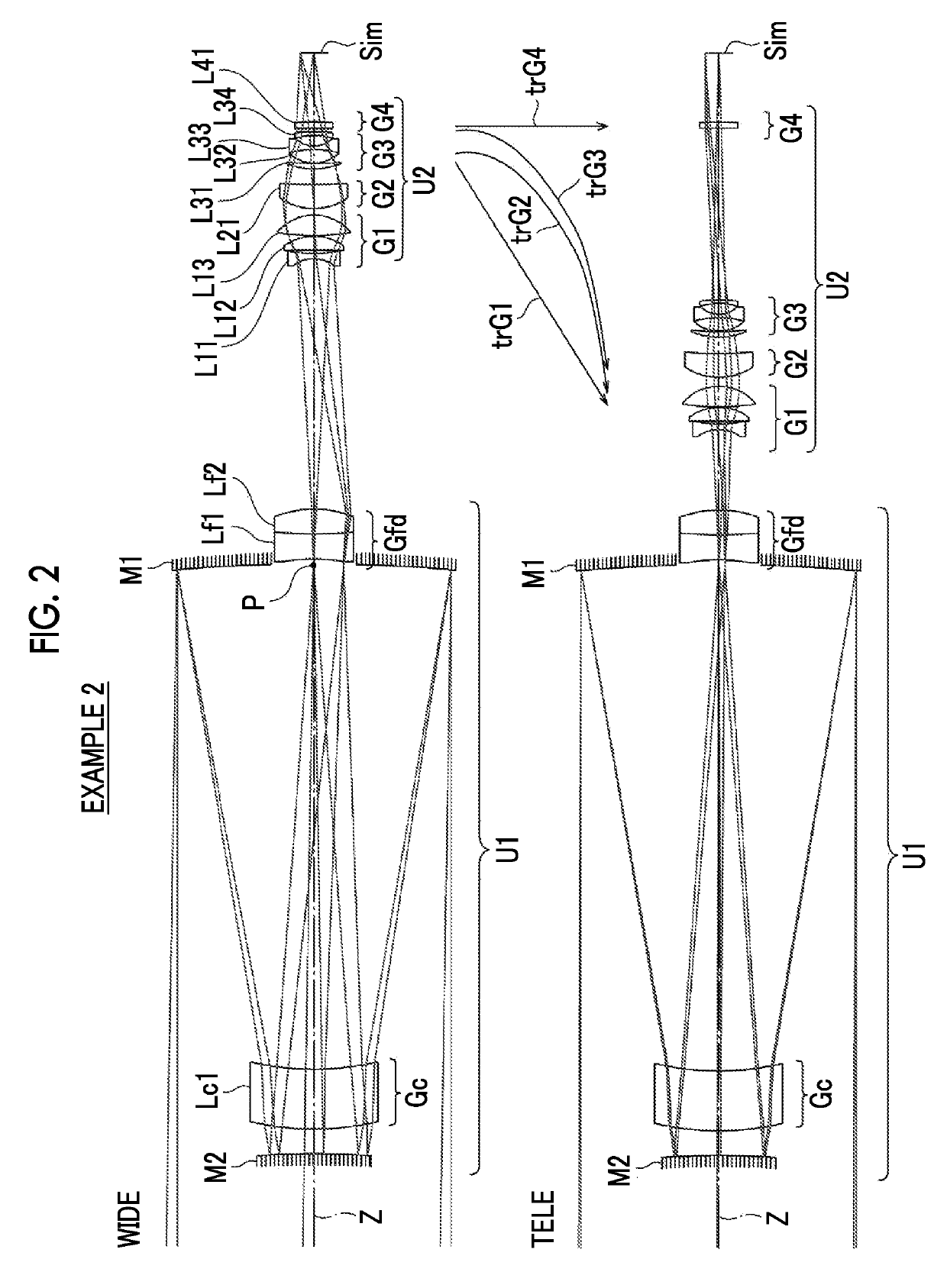
[0106]FIG. 2 shows a cross-sectional view and an optical path of the variable magnification optical system of Example 2. The variable magnification optical system of Example 2 has the same configuration as the outline of the variable magnification optical system of Example 1. Table 4 shows basic lens data of the variable magnification optical system of Example 2, Table 5 shows specification and variable surface distances, and FIG. 12 shows aberration diagrams thereof.
TABLE 4Example 2Surface numberrdMaterialNdνdθgFθCt 1 (Reflective−940.33887−295.360surface) 2163.45951−35.000SFSL5_OHARA1.48749070.230.53000.8924 3158.26945−11.507 4 (Reflective−492.1146311.507surface) 5158.2694535.000SFSL5_OHARA1.48749070.230.53000.8924 6163.45951295.560 7 (Intermediate∞2.640image) 8−98.8326914.797SNBH56_OHARA1.85478024.800.61220.6739 9186.0357414.407SLAH88_OHARA1.91650031.600.59110.705910−63.52799D1011−20.221943.200SLAL59_OHARA1.73399751.470.54860.80671270.080511.80813−677.798318.251SFPL53_OHARA1.43875...
example 3
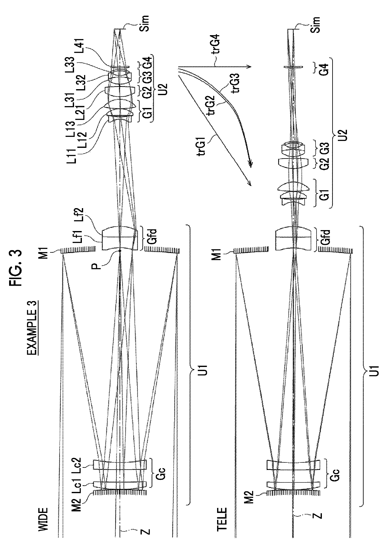
[0107]FIG. 3 shows a cross-sectional view and an optical path of the variable magnification optical system of Example 3. The variable magnification optical system of Example 3 is different from the variable magnification optical system of Example 1 in that the correction lens group Gc consists of two lenses Lc1 and Lc2 and the third lens group G3 consists of three lenses L31 to L33. The other configuration is the same as the outline of the variable magnification optical system of Example 1. Table 6 shows basic lens data of the variable magnification optical system of Example 3, Table 7 shows specification and variable surface distances, and FIG. 13 shows aberration diagrams thereof.
TABLE 6Example 3Surface numberrdMaterialNdνdθgFθCt 1 (Reflective−922.75595−294.382surface) 2189.54097−10.000SFSLS_OHARA1.48749070.230.53000.8924 31188.04152−17.474 4775.56532−10.000SFSL5_OHARA1.48749070.230.53000.8924 5168.65411−0.200 6 (Reflective−483.321430.200surface) 7168.6541110.000SFSL5_OHARA1.48749...
PUM
 Abstract
Description
Claims
Application Information
 - R&D
- Intellectual Property
- Life Sciences
- Materials
- Tech Scout
- Unparalleled Data Quality
- Higher Quality Content
- 60% Fewer Hallucinations
Browse by: Latest US Patents, China's latest patents, Technical Efficacy Thesaurus, Application Domain, Technology Topic, Popular Technical Reports.
© 2025 PatSnap. All rights reserved.Legal|Privacy policy|Modern Slavery Act Transparency Statement|Sitemap|About US| Contact US: help@patsnap.com