Cutting method and cutting tool
a cutting tool and cutting method technology, applied in the direction of manufacturing tools, turning machine accessories, liquid/solution decomposition chemical coatings, etc., can solve the problems of shortening the tool life, affecting the cutting effect, so as to reduce the risk of cutting, and prevent the cutting tool from being worn.
- Summary
- Abstract
- Description
- Claims
- Application Information
AI Technical Summary
Benefits of technology
Problems solved by technology
Method used
Image
Examples
first embodiment
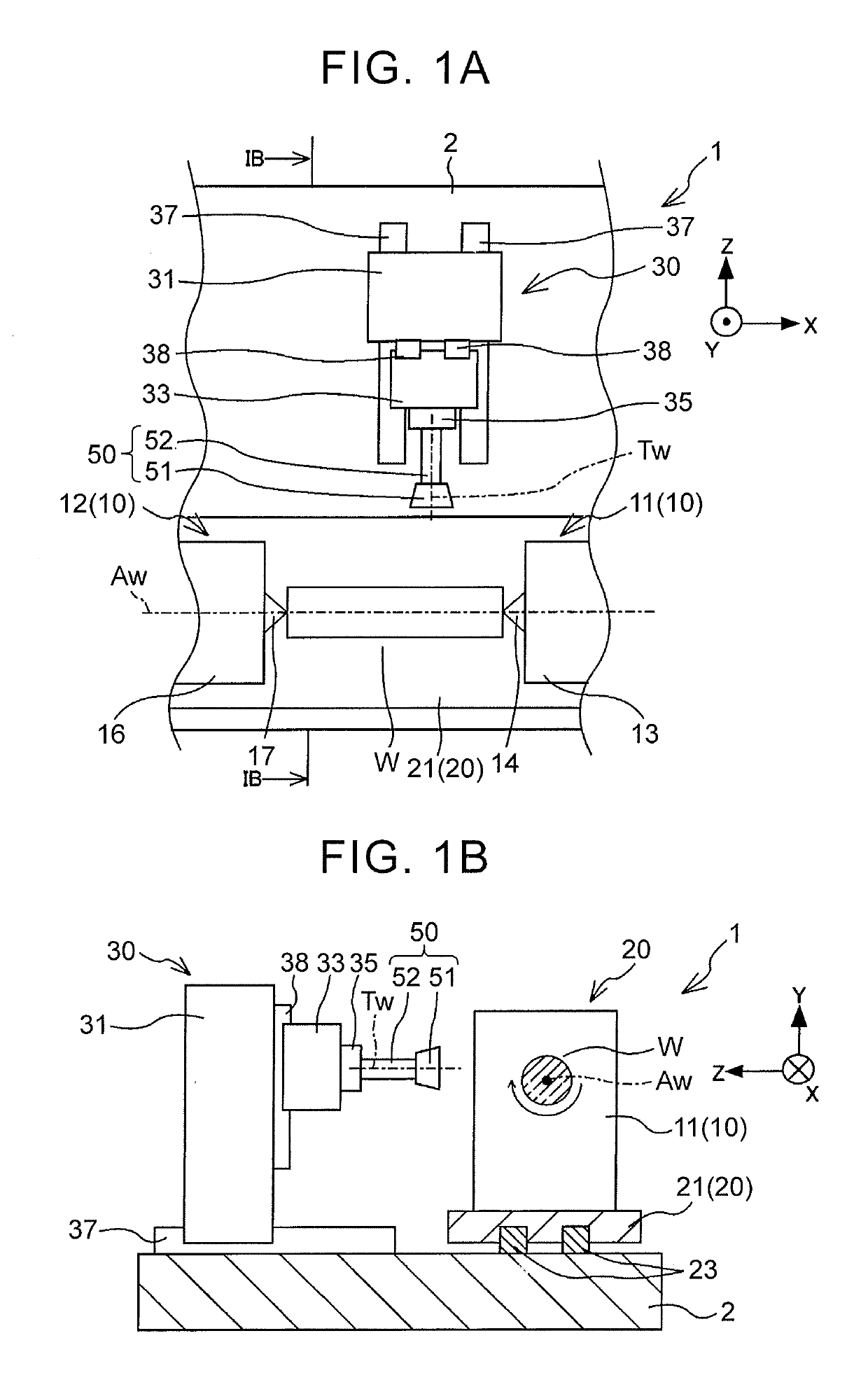
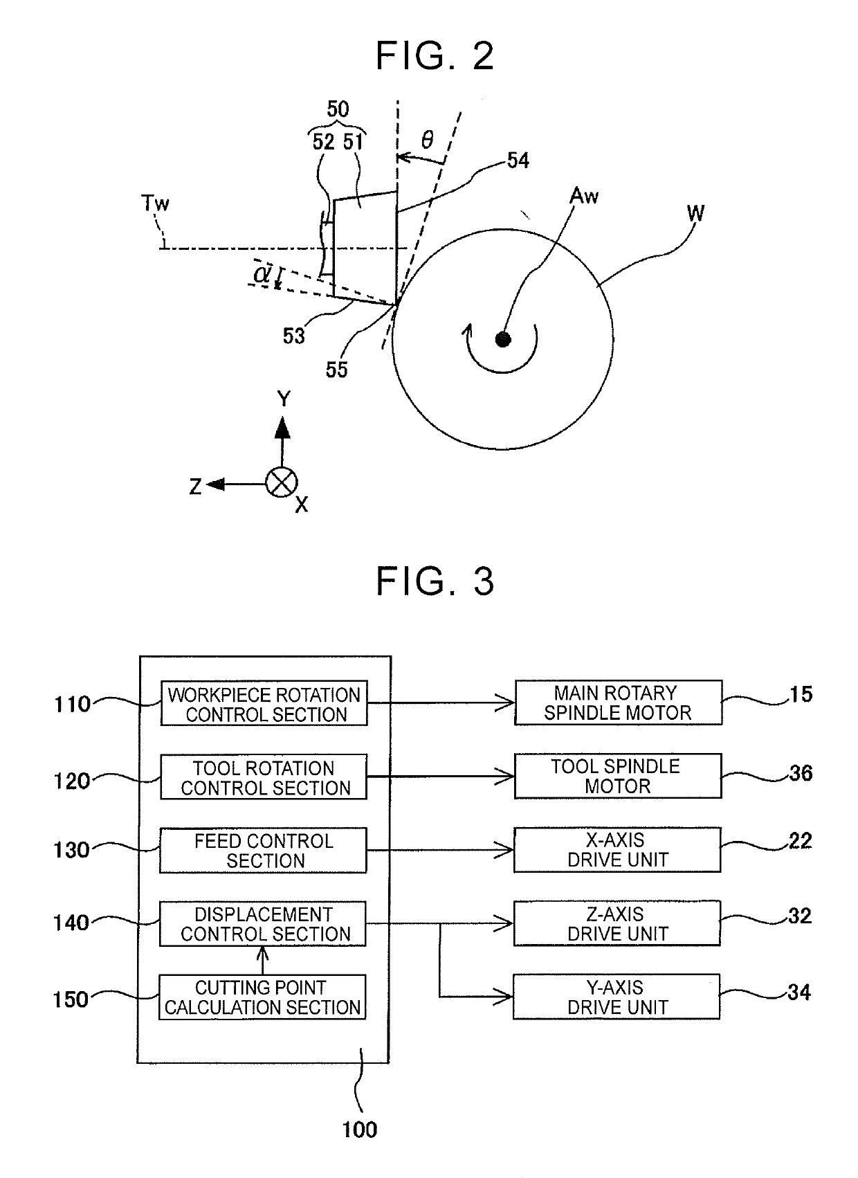
[0043]A description will hereinafter be made on embodiments, to each of which a cutting method according to the disclosure is applied, with reference to the drawings. Referring now to FIG. 1A to FIG. 3, a description will be made on a configuration of a cutting apparatus 1 used for a cutting method in the disclosure.
[0044]As shown in FIG. 1A and FIG. 1B, the cutting apparatus 1 is a four-axis machining center having three linear axes (an X-axis, a Y-axis, and a Z-axis) that are orthogonal to each other and one rotational axis (an unillustrated C-axis). The cutting apparatus 1 includes a workpiece retainer 10, a workpiece feeder 20, a tool retainer 30, and a controller 100 as main components.
[0045]The workpiece retainer 10 retains a workpiece W in such a manner as to allow rotation of the workpiece W. The workpiece retainer 10 includes a headstock 11 and a tailstock 12. The headstock 11 supports an axial end side (a right side in FIG. 1A) of the workpiece W in such a manner as to all...
second embodiment
[0083]As described above, in the ring-shaped tool 50 of the second embodiment, it is possible to suppress the deposited material from being deposited on the end surface 54 by reducing the surface roughness of the end surface 54.
[0084]In the second embodiment, the description has been made on the case where the deposition of the deposited material on the end surface 54 is suppressed by reducing the surface roughness of the end surface 54. In a third embodiment, the deposition of the deposited material on an end surface 254 is suppressed by setting the clearance angle θ, which is defined by the end surface 254 and the workpiece W, to be equal to or larger than a specified angle. Here, except for some of the components, the same components as those in the above embodiments will be denoted by the same reference numerals, and the description thereon will not be made.
third embodiment
[0085]As shown in FIG. 7, in a ring-shaped tool 250 of the third embodiment, the end surface 254 of a tool body 251 is formed in a tapered shape that is inclined in such a manner as to increase a clearance between the end surface 254 and an imaginary plane that is orthogonal to a rotation axis of the ring-shaped tool 250 and includes the cutting edge 55 as directed inward in a radial direction of the tool body 251 from the cutting edge 55. In the following description, an angle defined by the end surface 254 and the imaginary plane is defined as a tool clearance angle δ.
[0086]In this case, as shown in FIG. 8, in the cutting apparatus 1, while a rake angle defined by the outer circumferential surface 53 and the worked surface of the workpiece W is set at the same angle, the clearance angle δ defined by the end surface 254 and the worked surface of the workpiece W can be set to a larger angle than that in the ring-shaped tool (see FIG. 5A), the end surface of which is formed in a flat...
PUM
| Property | Measurement | Unit |
|---|---|---|
| arithmetical surface roughness | aaaaa | aaaaa |
| temperature | aaaaa | aaaaa |
| surface roughness | aaaaa | aaaaa |
Abstract
Description
Claims
Application Information
 - R&D
- Intellectual Property
- Life Sciences
- Materials
- Tech Scout
- Unparalleled Data Quality
- Higher Quality Content
- 60% Fewer Hallucinations
Browse by: Latest US Patents, China's latest patents, Technical Efficacy Thesaurus, Application Domain, Technology Topic, Popular Technical Reports.
© 2025 PatSnap. All rights reserved.Legal|Privacy policy|Modern Slavery Act Transparency Statement|Sitemap|About US| Contact US: help@patsnap.com


