
Electric shelf

a technology of shelves and shelves, applied in the field of shelves, can solve the problems of difficulty in accessing placed items, difficulty in satisfying the requirements of ease of access and reducing occupied space, and serious trouble in sorting out items, and achieve the effects of convenient installation, stable structure, and convenient us

Active Publication Date: 2019-08-22
LOCTEK INC
View PDF61 Cites 3 Cited by
  • Summary
  • Abstract
  • Description
  • Claims
  • Application Information

AI Technical Summary

Benefits of technology

The electric shelf provides safer and more efficient access to items by reducing space occupation, saving time and labor, and offering a stable and cost-effective installation process.

Problems solved by technology

Sorting out the items could be a serious trouble in many situations since scattering the items about will further exaggerate the trouble.
Since the shelves are fixed, it is difficult to satisfy the requirement for ease of access and the requirement for reducing occupied space simultaneously.
Mounting the shelf at a higher height allows the user to pass under without occupying usable home space, but presents difficulty in accessing placed items.
Instability during the rising or declining of the shelf could cause the shelf to waggle and results in insecurity such as collision or even dropping of items on the shelf.
The ceiling type shelf also incurs difficulties during installation.
A user is usually unable to install the shelf alone.

Method used


Image

  • Electric shelf
  • Electric shelf
  • Electric shelf

Examples


first embodiment

[0051]In a first embodiment, the linear driving device 7 of the electric shelf as shown in FIG. 4 comprises a motor 5, a screw rod 72, a screw rod transmission component, and a screw rod nut 71. The screw rod 72 is drivably connected to the motor 5. The screw rod nut 71 is fixed to the guide sleeve 4 through the rail groove 11. A friction sheet is provided between the guide sleeve 4 and the column 1. A limiter 73 is provided on top of the column 1. In particular, the limiter 73 is a bearing connected to the top end of the screw rod 72. The bearing is used for vibration absorption and noise absorption. During usage, the axial output torque of a driving shaft of the motor 5 is laterally transmitted to the screw rod 72 by the screw rod transmission component. Then the screw rod nut 71 actuates the guide sleeve 4 to move vertically along the rail groove 11 on the column 1. A limit switch is attached to the motor 5 which is drivably connected to the screw rod nut 71 by a linking shaft. T...

second embodiment

[0052]In a second embodiment, the linear driving device 7 of the electric shelf as shown in FIGS. 5 and 6 comprises a motor 5, a wheel gear 71a and a rack gear 72a. The rack gear 72a is parallel with the column 1 and is fixed to the inner wall of the column 1. The motor 5 is drivably connected to a worm wheel and the wheel gear 71a by a motor worm 73. The rack gear 72a is engaged with the wheel gear 71a. A motor support 74 is fixed to the motor 5. The motor support 74 is fixed to the motor 5 on one end, and connected to the guide sleeve 4 through the rail groove 11 on the other end. During usage, the motor actuates the guide sleeve 4 to move vertically along the rack gear 72a through the transmission of the worm wheel and the wheel gear 71a.

third embodiment

[0053]In a third embodiment, the linear driving device 7 of the electric shelf as shown in FIGS. 7 and 8 comprises a fixed pulley 72b, a moving pulley 71b, a wire 73b, a wire coiler connected to the wire 73b and a motor 5 drivably connected to the wire 73b. In some embodiments, a plurality of moving pulleys 71b can form a group of moving pulleys. The number of moving pulleys 71b is not limited in this embodiment. A fixing component is connected to the group of moving pulleys. The fixing component is connected to the guide sleeve 4 through the rail groove 11. During usage, the wire 73b is driven by the motor 5 to actuate the group of moving pulleys. The group of moving pulleys enables vertical displacement of the guide sleeve 4 in the rail groove 11.


PUM


Abstract

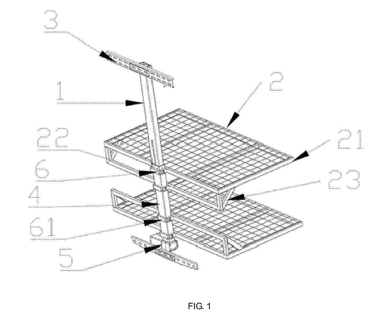
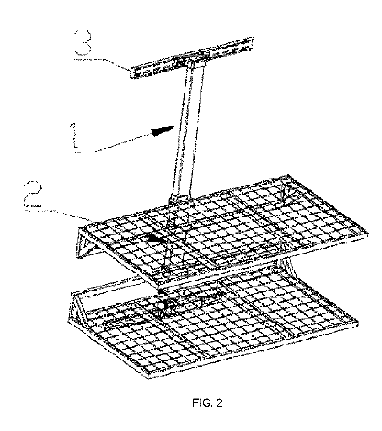
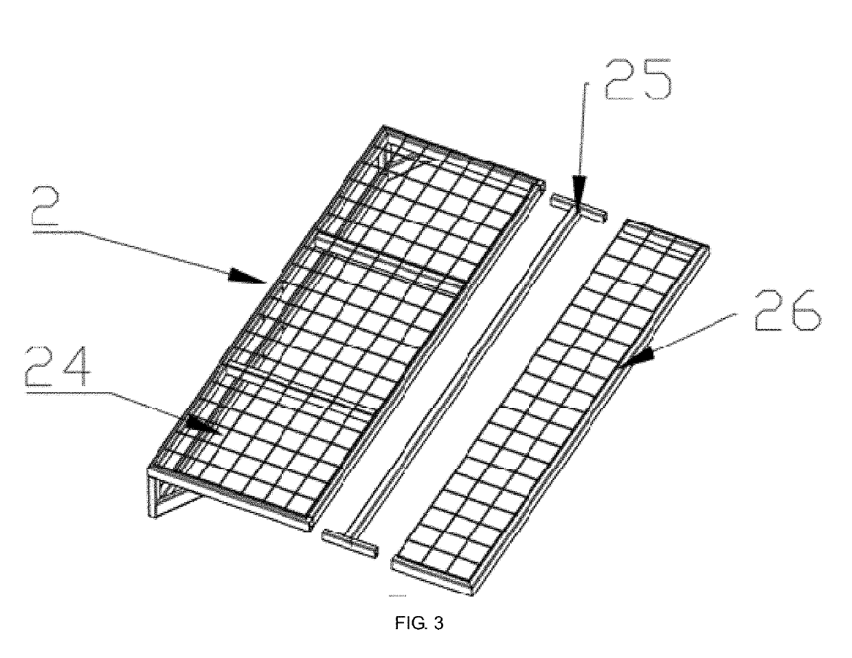
Embodiments of the present disclosure relate to an electric shelf which comprises at least one column to be installed on a wall, a slidable component arranged on the column to slide along the column vertically, at least one layer of shelf board component connected to the slidable component to move simultaneously with the slidable component, and a linear driving device connected to the slidable component and the column to actuate the slidable component to move relative to the column. Advantages of the present disclosure compared to prior arts include a simpler structure and less space occupied by the shelf board component.

Description

CROSS-REFERENCE TO RELATED APPLICATIONS[0001]This application is a continuation of U.S. utility patent application Ser. No. 15 / 695,009 with filing date Sep. 5, 2017, now pending, which is a continuation of International Patent Application No. PCT / CN2017 / 092380 with a filing date of Jul. 10, 2017, designating the United States, and further claims priority to Chinese Patent Application No. 201710337271.X with a filing date of May 14, 2017. The content of the aforementioned applications, including any intervening amendments thereto, are incorporated herein by reference.TECHNICAL FIELD[0002]The present disclosure relates to a shelf, and more particularly, to an electric shelf.BACKGROUND OF THE PRESENT INVENTION[0003]Daily necessities at home are growing in numbers due the continuous improvement of living standards. Sorting out the items could be a serious trouble in many situations since scattering the items about will further exaggerate the trouble. Therefore, shelves are being more wi...

Claims


Application Information

Patent Timeline
Patent Type & Authority Applications(United States)
IPC IPC(8): A47B57/06A47B51/00A47B96/14A47F5/08A47F5/10A47F3/08A47F5/00
CPCA47B57/06A47B51/00A47B96/14A47F5/08A47F5/103A47F3/08A47F5/0081A47B96/021A47B96/028A47B95/008A47B2200/0056
Inventor XIANG, LEHONGLIN, TAOWANG, SONGLI
Owner LOCTEK INC
Learn More