
Modular smoking device

a smoking device and module technology, applied in the field of smoking devices, can solve the problems of ineffective and cost-effective solutions, devices can produce unwanted, harmful, and potentially toxic byproducts, and achieve the effect of efficient vaporization of materials

Active Publication Date: 2019-08-15
MCCOY DAVID
View PDF6 Cites 8 Cited by
  • Summary
  • Abstract
  • Description
  • Claims
  • Application Information

AI Technical Summary

Benefits of technology

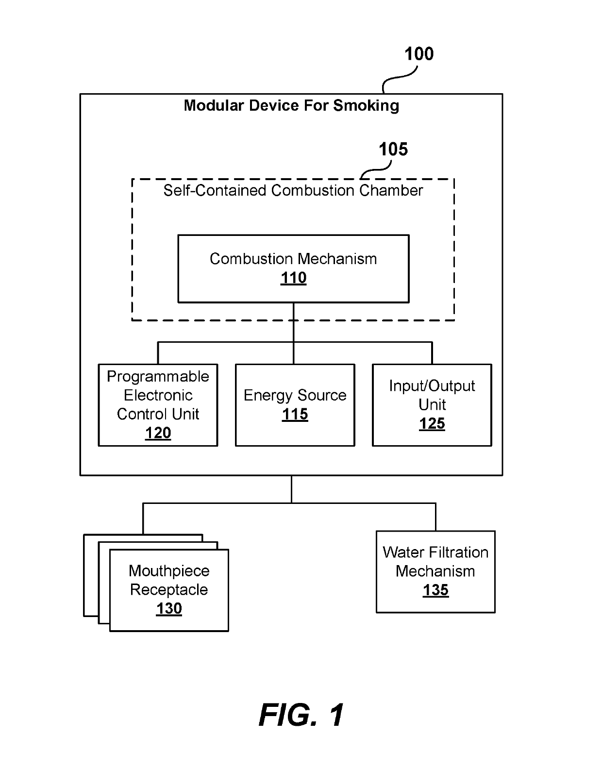
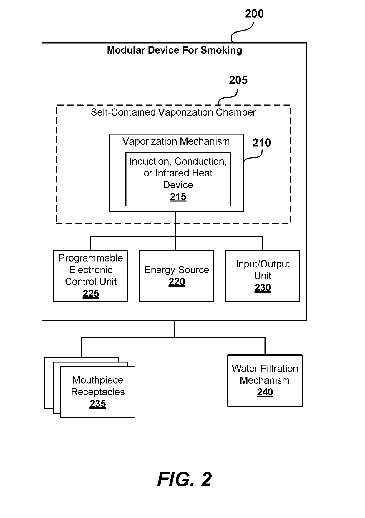
This patent is about a smoking device that can burn or vaporize certain materials like tobacco or cannabis for users to inhale. The technology allows for controlled burning or vaporization at specific temperatures to prevent harmful byproducts. The device has a self-contained chamber for holding the material and a vaporization mechanism powered by an energy source. The vaporization mechanism provides targeted vaporization of the material, resulting in the active ingredients being consumed by inhaling the vapor. The device is programmable to create targeted heat to efficiently vaporize the material based on the amount of material and type of material. Overall, the technology allows for intelligent smoking and vaporization of various materials in a safe and controlled way.

Problems solved by technology

Traditionally, the smoking devices lack temperature control over combustion of tobacco, plant, or other smokeable materials.
As such, research shows that these devices can produce unwanted, harmful, and potentially toxic byproducts upon inappropriately combusting the smokeable materials.
Although there were some attempts to solve that problem, such as by introducing filters, there are still no efficient and cost-effective solutions.

Method used


Image

  • Modular smoking device
  • Modular smoking device
  • Modular smoking device

Examples


Embodiment Construction

[0029]The following detailed description of embodiments includes references to the accompanying drawings, which form a part of the detailed description. Approaches described in this section are not prior art to the claims and are not admitted to be prior art by inclusion in this section. The drawings show illustrations in accordance with example embodiments. These example embodiments, which are also referred to herein as “examples,” are described in enough detail to enable those skilled in the art to practice the present subject matter. The embodiments can be combined, other embodiments can be utilized, or structural, logical and operational changes can be made without departing from the scope of what is claimed. The following detailed description is, therefore, not to be taken in a limiting sense, and the scope is defined by the appended claims and their equivalents.

[0030]The consumption of tobacco, cannabis, and related products is dynamically changing and will continue changing o...


PUM

PropertyMeasurementUnit
electric dischargeaaaaaaaaaa
electric poweraaaaaaaaaa
energyaaaaaaaaaa

Abstract

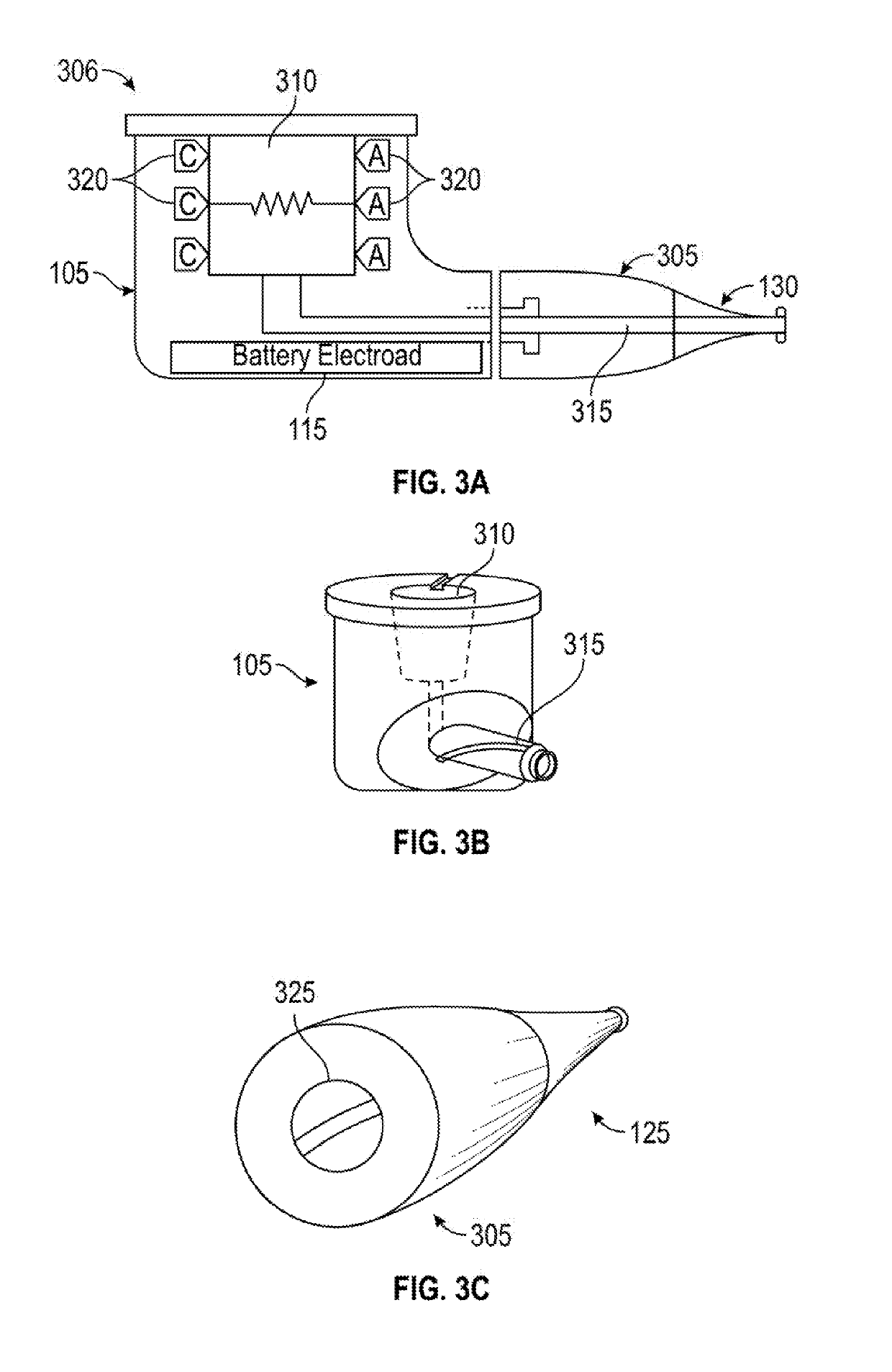
Modular smoking devices that generate vapors of certain materials, such as tobacco or cannabis are disclosed. The technology provides for intelligent ignition, combustion, or vaporization of given material at the appropriate temperatures that prevent generation of harmful and unwanted byproducts. According to one embodiment, the modular smoking device comprises a self-contained combustion chamber to hold the material, a combustion mechanism integrated with the self-contained combustion chamber, and an energy source, such as a rechargeable battery, to power the combustion mechanism. The combustion mechanism is configured to provide targeted combustion of the material, where the active ingredients generated upon the combustion are consumed by inhaling a smoke or vapor resulting from the combustion or vaporization. The self-contained combustion chamber includes a lighterless combustion mechanism such as a piezoelectric lighter or a Tesla coil lighter that is designed to arc an electric discharge through the material in the self-contained combustion chamber.

Description

TECHNICAL FIELD[0001]This disclosure generally relates to smoking devices. More particularly, this disclosure relates to modular smoking devices having a self-contained, self-powered combustion or vaporization chamber.DESCRIPTION OF RELATED ART[0002]The approaches described in this section could be pursued, but are not necessarily approaches that have been previously conceived or pursued. Therefore, unless otherwise indicated herein, the approaches described in this section are not prior art to the claims in this application and are not admitted to be prior art by inclusion in this section.[0003]Smoking and inhalation devices are well known for providing flavored vapor from a smokeable material to a user for therapeutic purposes or smoking pleasure. Some common smoking devices include a smoking pipe, a cigarette holder, a tobacco pipe, a bong, a water pipe, an electronic cigarette (e-cigarette), and a vaporizer. Traditionally, the smoking devices lack temperature control over combus...

Claims


Application Information

Patent Timeline
Patent Type & Authority Applications(United States)
IPC IPC(8): A24F1/24A24F47/00A24D1/14A24F1/28A24F1/32A24F1/30A24F1/06A24B15/16B65D75/36A61M15/00A61M15/06A24F40/20A24F40/48A24F40/50
CPCA24F1/24A24F47/008A24D1/14A24F1/28A24F1/32A24F1/30A24F1/06A24B15/16B65D75/36A61M15/0048A61M15/06A61M2205/123A61M2205/3653A61M2205/8206A61M15/0016A61M15/0018A61M15/02A61M11/042A61M15/0081A61M15/0083A61M2205/583A61M2205/368A61M15/0066A61M2205/6018A61M2205/502A61M2205/3368A61M2205/582A24F40/48A24F40/50A24F40/20H05B7/18A61J1/035
Inventor MCCOY, DAVID
Owner MCCOY DAVID
Learn More