
Power storage device

a power storage device and power technology, applied in the direction of mechanical energy handling, synchronous generators with multiple outputs, magnetic circuits characterised by magnetic materials, etc., can solve the problems of poor generating efficiency of generating units and large size, and achieve the effect of enhancing generating efficiency and rotating more smoothly

Active Publication Date: 2019-08-08
RONG SHIN JONG
View PDF0 Cites 2 Cited by
  • Summary
  • Abstract
  • Description
  • Claims
  • Application Information

AI Technical Summary

Benefits of technology

The present invention is a power storage device that can rotate smoothly and generate electricity with high efficiency. It uses a magnetic levitation effect between two magnets to achieve this. The device has a rotating shaft that can generate a corresponding rotation, resulting in a smoother and more efficient rotation.

Problems solved by technology

However, the generator using natural resources as mentioned above generates enough electricity to supply all kinds of large-scale machinery for operation, but it is large in size.
However, in the above creation, the rotating shaft of the drive unit is not smooth during operation, so that the generating efficiency of the generating units is poor.

Method used


Image

  • Power storage device
  • Power storage device
  • Power storage device

Examples


Embodiment Construction

[0013]Embodiments of the present invention will now be described, by way of example only, with reference to the accompanying drawings.

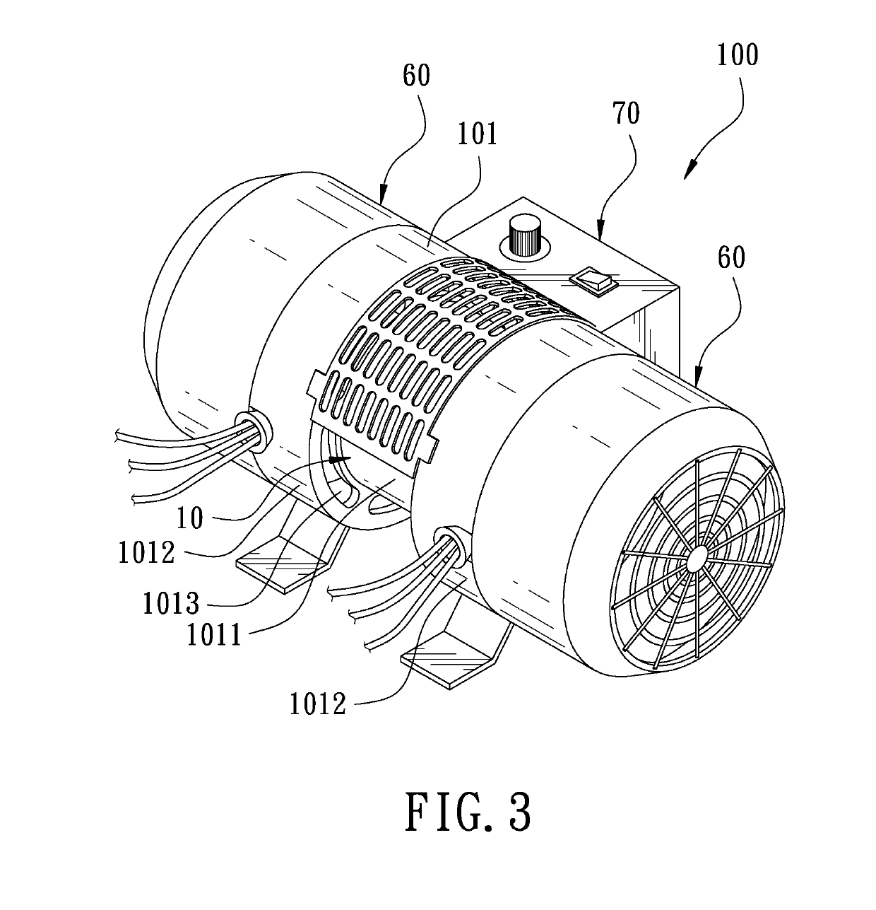
[0014]FIG. 3 is a perspective view in accordance with a preferred embodiment of the present invention. FIG. 4 is a perspective view in accordance with the preferred embodiment of the present invention, without generating units. The present invention discloses a power storage device 100. The power storage device 100 comprises a housing 101, a drive unit 10, a first permanent magnet assembly 20, a first auxiliary magnet 30, a second permanent magnet assembly 40, a second auxiliary magnet 50, two generating units 60, and a power supply unit 70.

[0015]The housing 101 has a hollow cylindrical body. The outer diameter of a middle section of the housing 101 is less than the outer diameter of two sides of the housing 101. Therefore, the middle section of the housing 101 is formed with a reduced portion 1011, and the two sides of the housing 101 are formed with...


PUM


Abstract

A power storage device includes a drive unit, a generating unit, and a power supply unit. The drive unit has a rotating shaft and is disposed in a housing. The rotating shaft is provided with a plurality of first permanent magnets. The housing is provided with a first auxiliary magnet corresponding to the first permanent magnets. Corresponding surfaces of the first permanent magnets and the first auxiliary magnet have the same magnetic pole. Through the repulsive force between the first permanent magnets and the first auxiliary magnet to generate a magnetic levitation effect, the rotating shaft can generate a corresponding rotation and the rotating shaft can be rotated more smoothly to increase its rotational speed and smoothness to improve generating efficiency and reduce electricity consumption.

Description

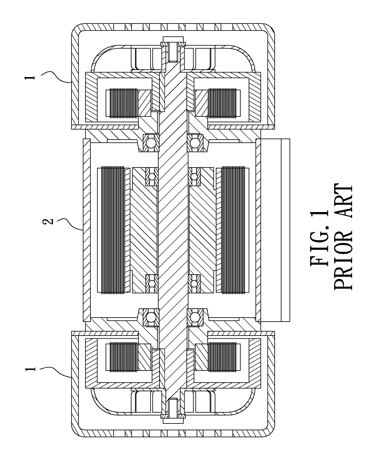
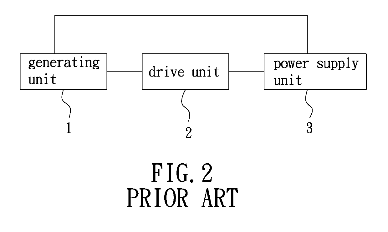
FIELD OF THE INVENTION[0001]The present invention relates to a power storage device, and more particularly to a power storage device with high-efficiency generating capability.BACKGROUND OF THE INVENTION[0002]When a conventional generator is running, natural energy, such as solar power, wind power and hydroelectric power, is used to convert natural energy into required electricity. However, the generator using natural resources as mentioned above generates enough electricity to supply all kinds of large-scale machinery for operation, but it is large in size. Therefore, when the generator is applied to bicycles, electric cars or small household appliances, there is a need for improvement.[0003]In view of the above, some improvements have been made to the above drawbacks. As shown in FIG. 1 and FIG. 2, a permanent magnet synchronous generator mainly includes two generating units 1, a drive unit 2, and a power supply unit 3. The power supply unit 3 is connected to the drive unit 2 to p...

Claims


Application Information

Patent Timeline
Patent Type & Authority Applications(United States)
IPC IPC(8): H02K7/09H02K1/02H02K5/20H02K7/08H02K9/16H02K11/00H02K21/48
CPCH02K7/09H02K1/02H02K5/20H02K7/083H02K9/16H02K11/0094H02K21/48H02K53/00H02K5/207
Inventor BU, DER-GUEYLIU, JIA-QING
Owner RONG SHIN JONG
Learn More