
Cord switch

a technology of cord switch and splice, which is applied in the direction of insulated conductors, cables, instruments, etc., can solve the problems of tubular member buckling and electrode wires being brought into contact, and achieve the effect of suppressing the buckling of the tubular member

Pending Publication Date: 2019-07-25
PROTERIAL LTD
View PDF8 Cites 0 Cited by
  • Summary
  • Abstract
  • Description
  • Claims
  • Application Information

AI Technical Summary

Benefits of technology

This patent describes a cord switch that prevents the tubular member from getting bent or buckled. The technical effect of this invention is to provide a more durable and reliable switch for use in various applications.

Problems solved by technology

However, when the cord switch was installed along a curved portion having a small bending radius as described above, there was the problem that the tubular member buckled.
In this case, there is a possibility that the problem occurs that the electrode wires are brought into contact with each other beforehand by the buckling of the tubular member, even though no foreign object (e.g., human body) is in contact with the cord switch.

Method used


Image

  • Cord switch
  • Cord switch
  • Cord switch

Examples


embodiments

[0022]An embodiment of the present invention will be described below with reference to the accompanying drawings.

first embodiment

[0023](Whole Configuration of a Cord Switch)

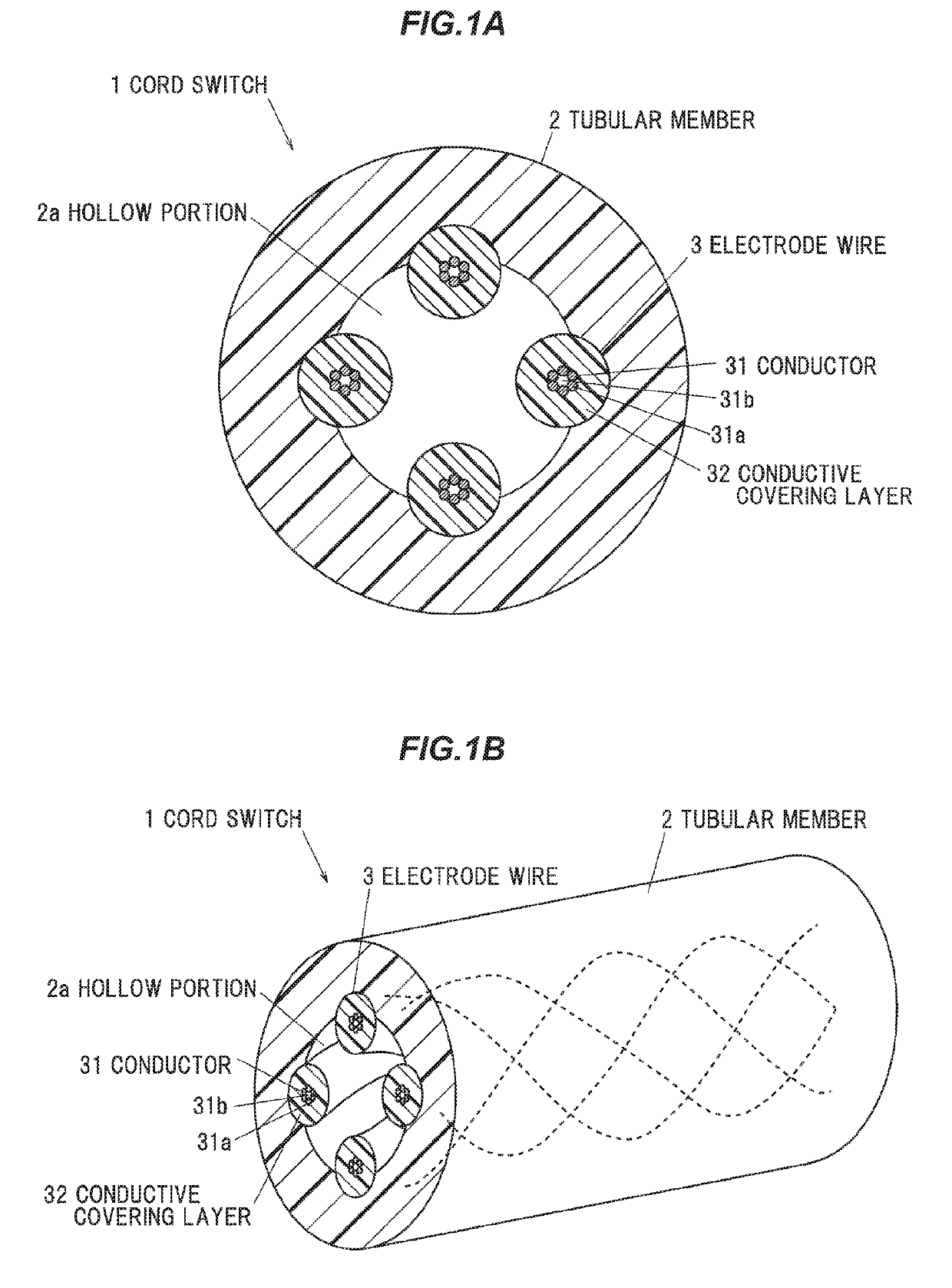
[0024]FIG. 1A is a cross sectional view perpendicular to a longitudinal direction showing a cord switch according to a first embodiment of the present invention, and FIG. 1B is a perspective view showing the cord switch according to the first embodiment of the present invention

[0025]As shown in FIGS. 1A and 1B, the cord switch 1 includes a hollow tubular member 2 having elasticity and insulation properties, and a plurality of electrode wires 3 arranged opposite to an inner side of the tubular member 2 and spaced apart by elastic force of the tubular member 2.

[0026]The tubular member 2 is formed in a cylindrical shape having a hollow portion 2a along the longitudinal direction (in a cylindrical shape with no pressing force being externally applied thereto). The tubular member 2 is desirably made of a material having small compression permanent distortion and excellent in flexibility, cold resistance, water resistance, chemical resistance, w...

second embodiment

[0047](Overall Configuration of a Cord Switch)

[0048]FIG. 5A is a cross-sectional view perpendicular to a longitudinal direction showing a cord switch according to a second embodiment of the present invention, and FIG. 5B is a perspective view showing the cord switch according to the second embodiment of the present invention

[0049]As shown in FIGS. 5A and 5B, the cord switch 1A includes a hollow tubular member 2 having elasticity and insulation properties, and a plurality of electrode wires 3A arranged opposite to an inner side of the tubular member 2 and spaced apart by elastic force of the tubular member 2. The cord switch 1A according to the second embodiment is different from the cord switch 1 according to the first embodiment in that the electrode wires 3A are provided with a linear body 31c instead of the conductor hollow portion 31b of the electrode wires 3. In the description relating to the second embodiment, the same reference numerals are used for the elements exhibiting t...


PUM

PropertyMeasurementUnit
outer diameteraaaaaaaaaa
elasticityaaaaaaaaaa
insulating propertiesaaaaaaaaaa

Abstract

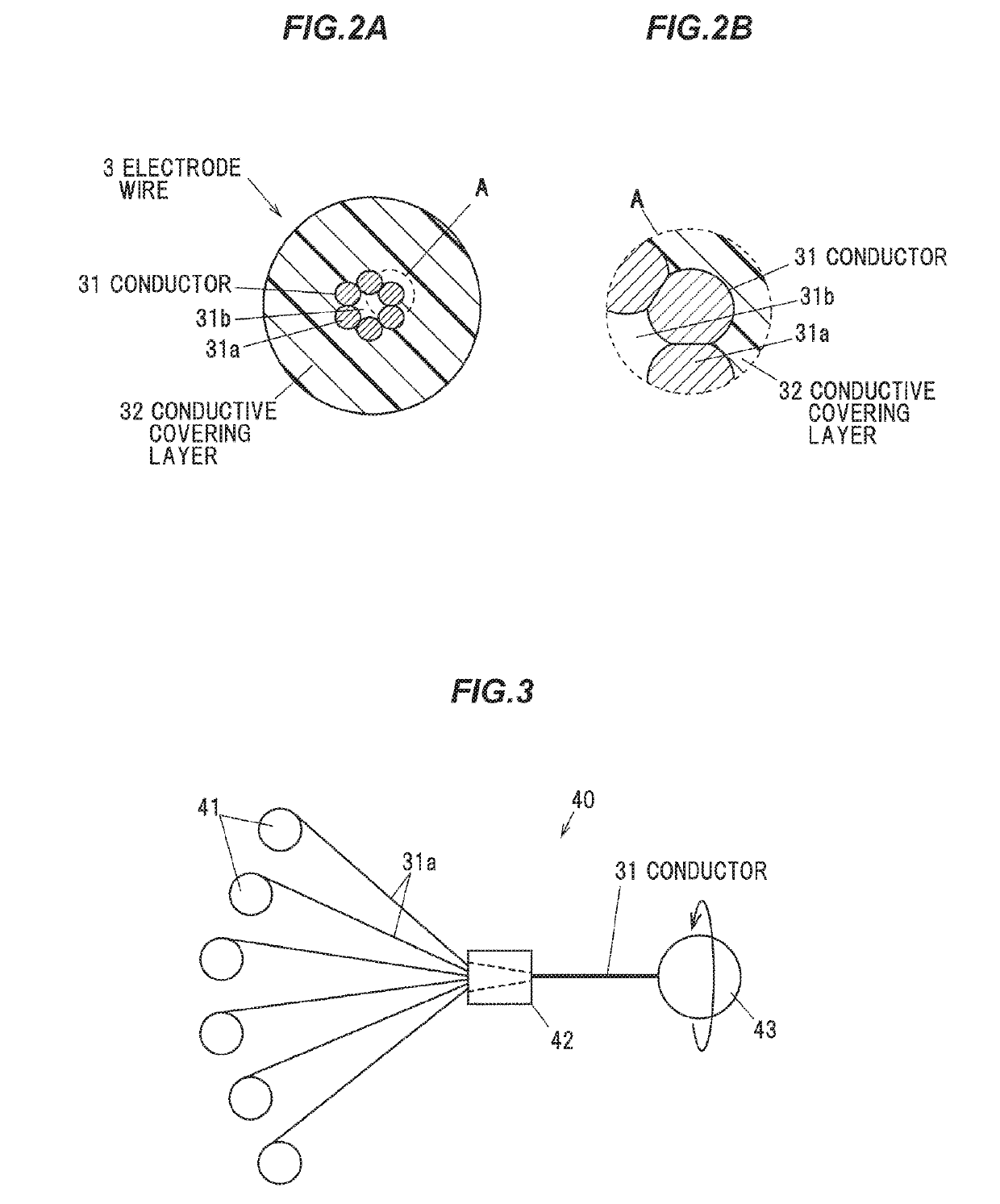
A cord switch is composed of a hollow tubular member having elasticity and insulating properties, and a plurality of electrode wires disposed opposite an inner side of the tubular member and spaced apart by elastic force of the tubular member. The plurality of electrode wires each include a conductor formed by stranding a plurality of metal wires together. All of the metal wires constituting the conductors are helically stranded together.

Description

CROSS-REFERENCE TO RELATED APPLICATIONS[0001]The present application is based on Japanese patent application No. 2018-009614 filed on Jan. 24, 2018 and Japanese patent application No. 2018-022693 filed on Feb. 13, 2018, the entire contents of which are incorporated herein by reference.BACKGROUND OF THE INVENTION1. Field of the Invention[0002]The present invention relates to a cord switch.2. Description of the Related Art[0003]A cord switch is conventionally used to prevent a foreign object (e.g., a human body) from being caught in a sliding door or the like of a vehicle (see, e.g., WO2015 / 194030). In order to prevent a foreign object (e.g., a human body) from being caught in the sliding door of the vehicle, the cord switch is installed along a door edge portion of the sliding door. The so-called “cord switch” is a cord-like sensor switch including a cable and typically used as a pressure-sensitive sensor.[0004]The cord switch described in WO2015 / 194030 includes a tubular member havi...

Claims


Application Information

Patent Timeline
Patent Type & Authority Applications(United States)
IPC IPC(8): H01B7/10H01B7/00H01H3/14
CPCH01B7/104H01B7/0009H01H3/142H01B13/0264H01H2003/143H01H2203/008H01H2203/022H01H17/02G01V3/02H01H9/04
Inventor SUGITA, KEISUKEABE
Owner PROTERIAL LTD
Learn More