
Device For Injecting A Liquid Product Having Simplified Assembly

Active Publication Date: 2019-07-25
NEMERA LA VERPILLIERE SAS
View PDF0 Cites 0 Cited by
  • Summary
  • Abstract
  • Description
  • Claims
  • Application Information

AI Technical Summary

Benefits of technology

This patent is about an automatic injection device that makes it easier to assemble and insert a syringe into. The device includes a support that holds the syringe and keeps it in place during use. The support is designed to protect the syringe from damage during assembly and use. The device also includes a mechanism that ensures the syringe is securely positioned and stays in place during use. This allows for the use of stronger springs and viscous liquids for injection. Additionally, the device has a mechanism that prevents the syringe from moving during use. Overall, the device simplifies the assembly and use of automatic injection devices, making it easier for manufacturers to equip them with complex apparatus.

Problems solved by technology

The syringe support in which the syringe is housed has a tubular general shape the diameter of which is close to that of the central part of the syringe; it is not always possible to insert the syringe in the syringe support after the two half-shells that constitute it have been assembled, because the flange and the cap are wider than the central part of the syringe and therefore wider than the inside diameter of the syringe support.

Method used


Image

  • Device For Injecting A Liquid Product Having Simplified Assembly
  • Device For Injecting A Liquid Product Having Simplified Assembly
  • Device For Injecting A Liquid Product Having Simplified Assembly

Examples


first embodiment

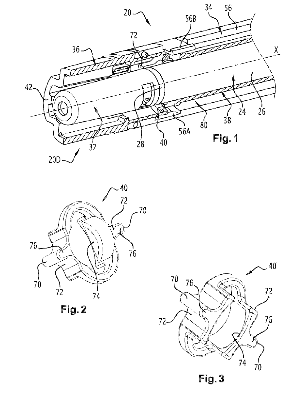
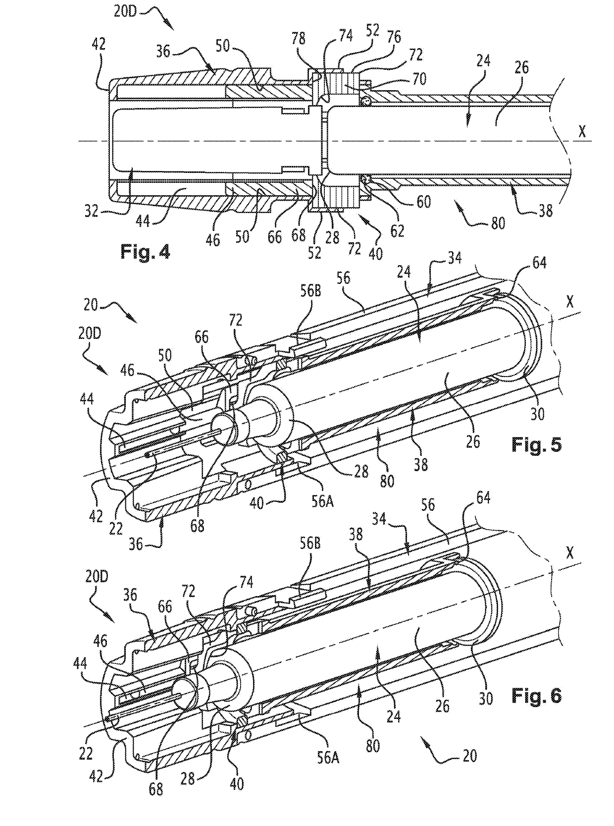
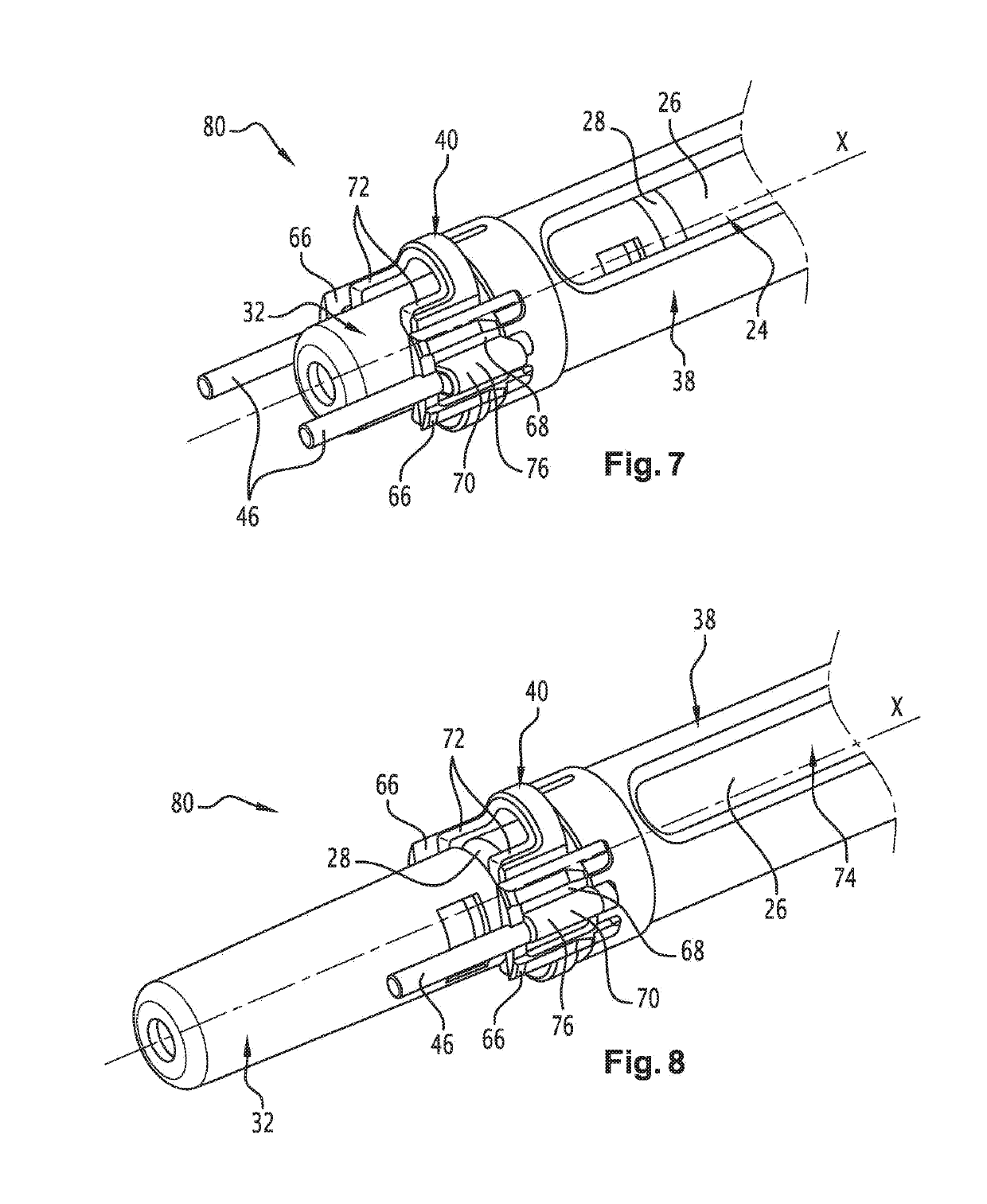
[0040]There is shown in FIGS. 1 to 10 a device 20 in accordance with the invention for injecting a liquid product. To be more precise, the injection device 20 is a medical device enabling the automatic administration of a liquid medication by injection.

[0041]Thus the injection device 20 is used to administer a liquid product to a patient, more particularly a pharmaceutical product administered by injection. This injection device 20 essentially has a cylindrical general shape with axis X. To perform an injection, the patient grasps the injection device 20 by one end and applies the other end of this injection device 20 against their skin. A series of movements of various members of the injection device 20 that are controlled automatically then leads to the insertion of an injection needle 22 of an injection syringe 24 into the skin of the patient and then the injection of its content through the injection needle 22.

[0042]Hereinafter, by proximal is meant an element of the injection d...

second embodiment

[0065]There will be described below, with reference to FIGS. 11 to 15, a distal part 20D of an injection device 20 in accordance with the invention. In this case, elements analogous to those of the preceding figures are designated by identical references.

[0066]In this embodiment, the elastic ring 62 is replaced by strips 86 fixed against the interior wall of the syringe support 38, for example made from TPE. These strips 86 have the same function as the elastic ring 62.

[0067]In contrast to the preceding embodiment, in this embodiment, the deformable ring 40 is urged elastically toward its cap passage configuration when it is not loaded. Moreover, the deformable ring 40 simply bears against the distal end of the syringe support 38. This enables the deformable ring 40 to be kinetically connected to the syringe support 38.

[0068]In fact, the deformable ring 40 is deformed from its protection cap 32 passage configuration to its injection syringe 24 axial immobilization configuration agai...


PUM


Abstract

A part of a device for injecting a liquid product having an end sleeve and a syringe support which is able to move with respect to the end sleeve. The syringe support is designed to bear an injection syringe fitted with a removable protective cap. A deformable ring is kinematically connected to the syringe support. This ring can be deformed elastically between a configuration which is designed to axially immobilize the injection syringe in the syringe support, and a configuration designed to allow the protective cap to pass through the deformable ring.

Description

FIELD OF THE INVENTION[0001]The present invention concerns the field of automatic liquid product injection devices, notably pharmaceutical liquid product injection devices.BACKGROUND OF THE INVENTION[0002]An automatic injection device is generally a medical device enabling the automatic administration of a liquid medication necessitating an injection. These devices in particular enable persons to inject themselves their dose of medication autonomously, for example persons suffering from rheumatoid arthritis, multiple sclerosis or diabetes or suffering an anaphylactic shock in the case of an allergy.[0003]One example of an automatic injection device is described in the document U.S. Pat. No. 8,734,402. The device comprises an injection syringe that contains the liquid product to be injected and is fitted with a needle, and a syringe support. It generally suffices to press the device briefly onto the skin of the patient to trigger penetration of the needle into the skin, followed by i...

Claims


Application Information

Patent Timeline
IPC IPC(8): A61M5/31A61M5/20A61M5/32
CPCA61M5/3137A61M5/2033A61M5/3202A61M2005/3139A61M2205/0216A61M2005/3142A61M5/20A61M2005/206A61M5/3204A61M5/326
Inventor DUGAND, PASCALSTAMP, KEVIN
Owner NEMERA LA VERPILLIERE SAS
Learn More