Injection device with dose indicator mechanism

a technology of injection device and indicator mechanism, which is applied in the direction of infusion syringes, intravenous devices, instruments, etc., can solve the problem of occupying a relatively large indicator area

Active Publication Date: 2019-07-18
NORTON HEALTHCARE
View PDF0 Cites 4 Cited by
  • Summary
  • Abstract
  • Description
  • Claims
  • Application Information

AI Technical Summary

Benefits of technology

The patent text describes a device that helps to accurately display the dose of a substance. It uses a tens wheel and a units wheel to increment the display. The device ensures that the tens wheel only moves when it is engaged with the units wheel, which prevents accidental movement and ensures a more accurate display.

Problems solved by technology

A disadvantage of using a number sleeve to indicate the dose is that the indicator area takes up a relatively large portion of the device and is generally centrally located, as illustrated in FIG. 2 of WO2014 / 166908.

Method used


Image

  • Injection device with dose indicator mechanism
  • Injection device with dose indicator mechanism
  • Injection device with dose indicator mechanism

Examples


example embodiment

Description of Example Embodiment

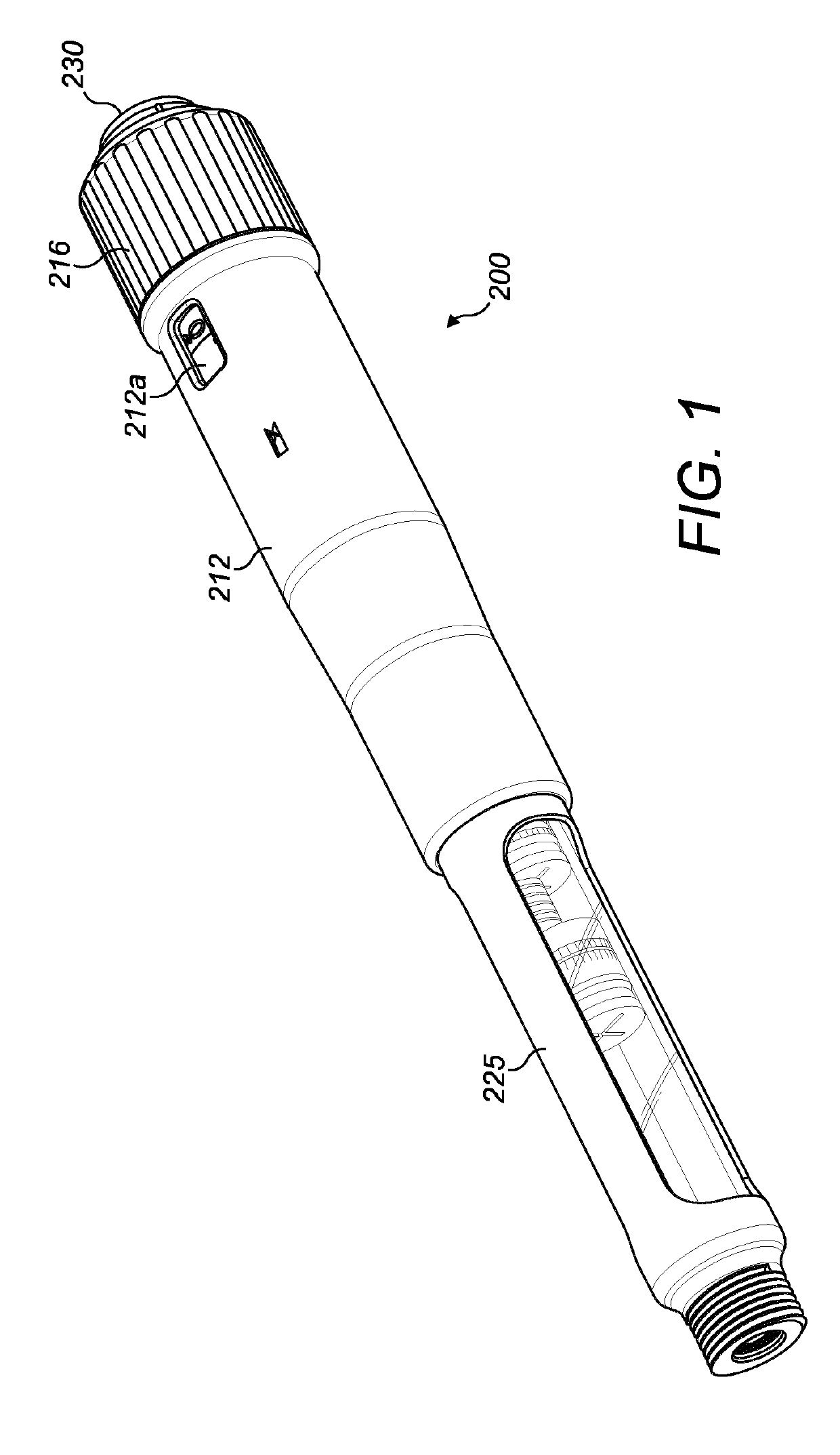
[0070]A non-limiting embodiment of an injection device according to the present invention is illustrated in FIGS. 1-21.

[0071]Referring to FIGS. 1-5, the injection device 200 includes a housing 212, a dose selector 216, a dose button 230 and dose button spring 231, a units wheel 218, a tens wheel 219, a ratchet pawl 217, a housing top cap 221, an odometer shuttle lock 222, a drive spring 220, a drive sleeve 240, a last dose nut 241, a drive clutch 250, a drive clutch spring 251, a leadscrew nut 252, a leadscrew 253 and a thrust bearing 254, all located concentrically about a common longitudinal axis L. The axis L extends between a front end 200a and a rear end 200b of the injection device 200.

[0072]The injection device 200 has a medicament cartridge 224 supported in a cartridge holder 225 at the front end 200a of the injection device. A needle or needle hub unit (not shown) can be connected to the cartridge holder. The cartridge is sealed by an axiall...


PUM


Abstract

An injection device comprises a housing, a dose indicator positioned within the housing and a dose selector operatively connectable to the dose indicator. The dose selector and the dose indicator are capable of cooperating with one another to set a dose to be ejected from the injection device. The dose indicator comprises an odometer including: i. a units (218) wheel operatively connected to the dose selector so that rotation of the dose selector also rotates the units wheel, and ii. a tens wheel (219) selectively engageable with the units wheel so that rotation of the units wheel also rotates the tens wheel. The dose indicator further comprises an axially-moveable shuttle lock (222) rotationally locked to the tens wheel and selectively engageable with the units wheel and the housing. The tens wheel is selectively engageable with the units wheel via said shuttle lock and, when the tens wheel is not engaged with the units wheel, the shuttle lock is rotationally locked to the housing.

Description

[0001]This disclosure relates to the field of dose indicator mechanisms for injection devices, preferably to dose indicator mechanisms having a torsion spring for assisting injection of a dose of medicament from an injection device.BACKGROUND[0002]Certain injection devices are required to have a visual indicator for the user so that the correct dose of medicament can be set and observed. This dose indicator commonly takes the form of a number sleeve, an example of which is described in U.S. Pat. No. 8,672,898. A rotatable sleeve with numbers printed along a helical line can be inspected through a window in the housing of the device, the window showing only one of the numbers at a time which corresponds to the dose set. However, U.S. Pat. No. 8,672,898 uses a linear compression spring. An example of a number sleeve in an injection device using a torsion spring is described in WO2014 / 166908.[0003]A disadvantage of using a number sleeve to indicate the dose is that the indicator area t...

Claims


Application Information

Patent Timeline
Patent Type & Authority Applications(United States)
IPC IPC(8): A61M5/315A61M5/20G06M1/04
CPCA61M5/31541A61M5/20A61M5/31583A61M5/31593A61M5/31553G06M1/042A61M5/3157A61M5/24A61M2005/3126A61M5/31535
Inventor DAVIES, JAMES ALEXANDERHART, OLIVERHEWSON, KARL JAMESSHENKER, JOSHUA ARIEH
Owner NORTON HEALTHCARE
Why Eureka
Try Eureka