
Grip-type pulse wave measuring device

a pulse wave and measuring device technology, applied in the field of grip-type pulse wave measuring devices, can solve the problems of difficult stably measuring pulse waves, limited use places, and unnatural movement, and achieve the effect of reducing the possibility of breakag

Pending Publication Date: 2019-07-11
MURATA MFG CO LTD
View PDF18 Cites 4 Cited by
  • Summary
  • Abstract
  • Description
  • Claims
  • Application Information

AI Technical Summary

Benefits of technology

The technical effect of this patent is to provide a grip-type pulse wave measuring device that allows the user to stably acquire pulse waves by naturally gripping the device with one hand. The device has a stopper that fixes the position of the thumb and prevents it from moving when the user grips the device. The user's index finger is guided to the pulse wave sensor by a step portion on the device, which also helps in fixing the position of the finger tip of the thumb. The device is designed ergonomically to minimize fatigue and prevent positional variations in the finger tip of the thumb. The device has a light shielding cover that prevents distortion light from entering the sensor while measuring. The cover can be automatically opened when the device is not gripped or closed when the device is used. The cover is fixed in the closed state when the device is not used to reduce the possibility of breakage.

Problems solved by technology

Accordingly, this pulse wave measuring device can be used only on, for example, a desk or the like, and there is a problem that the place of use is limited.
On the other hand, with the pulse wave measuring device disclosed in Patent Document 2, although limitation of the place of use is eliminated, it is necessary to insert the index finger into the pulse wave detector provided near the center of the main body portion while gripping the device by four fingers except the index finger, and thus an unnatural movement is forced.
Moreover, it is difficult to stably measure the pulse waves for a long time because of such an unnatural holding manner.

Method used


Image

  • Grip-type pulse wave measuring device
  • Grip-type pulse wave measuring device
  • Grip-type pulse wave measuring device

Examples


Embodiment Construction

[0033]Hereinafter, exemplary embodiments will be described in detail with reference to the accompanying drawings. It is noted that in the drawings, the same or corresponding parts are denoted by the same reference numerals. In addition, in each of the drawings, the same elements are denoted by the same reference numerals, and overlapped description thereof will be omitted.

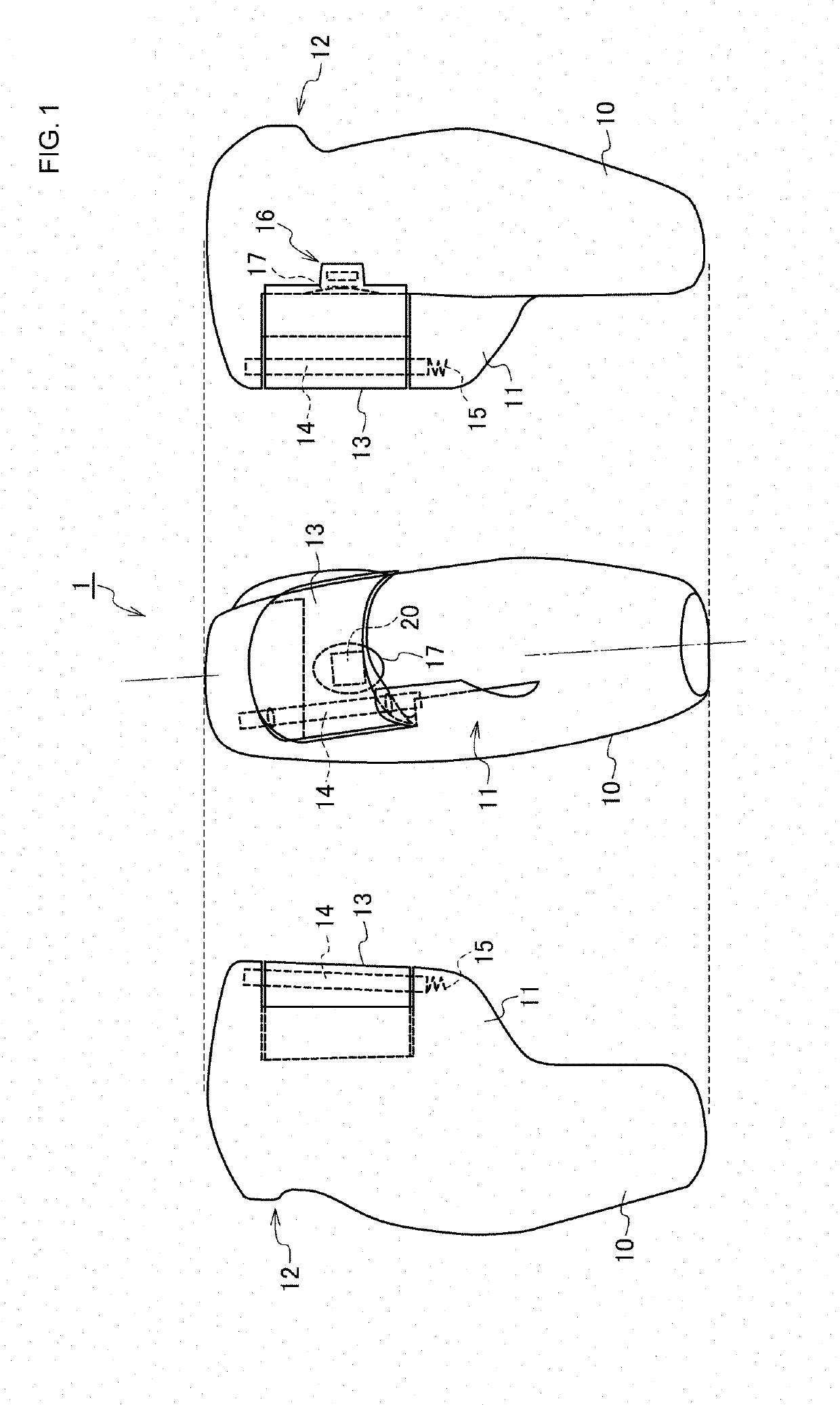
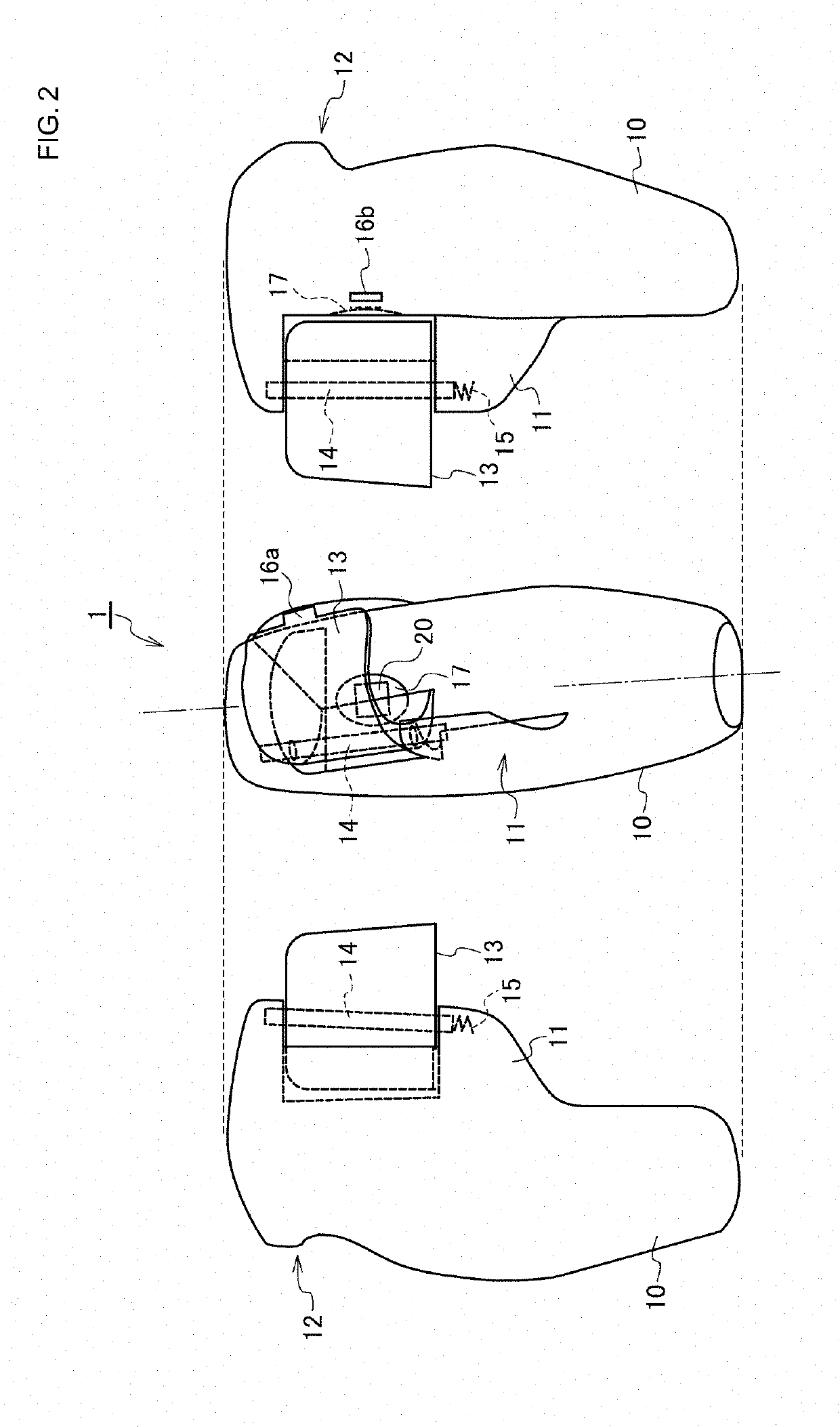
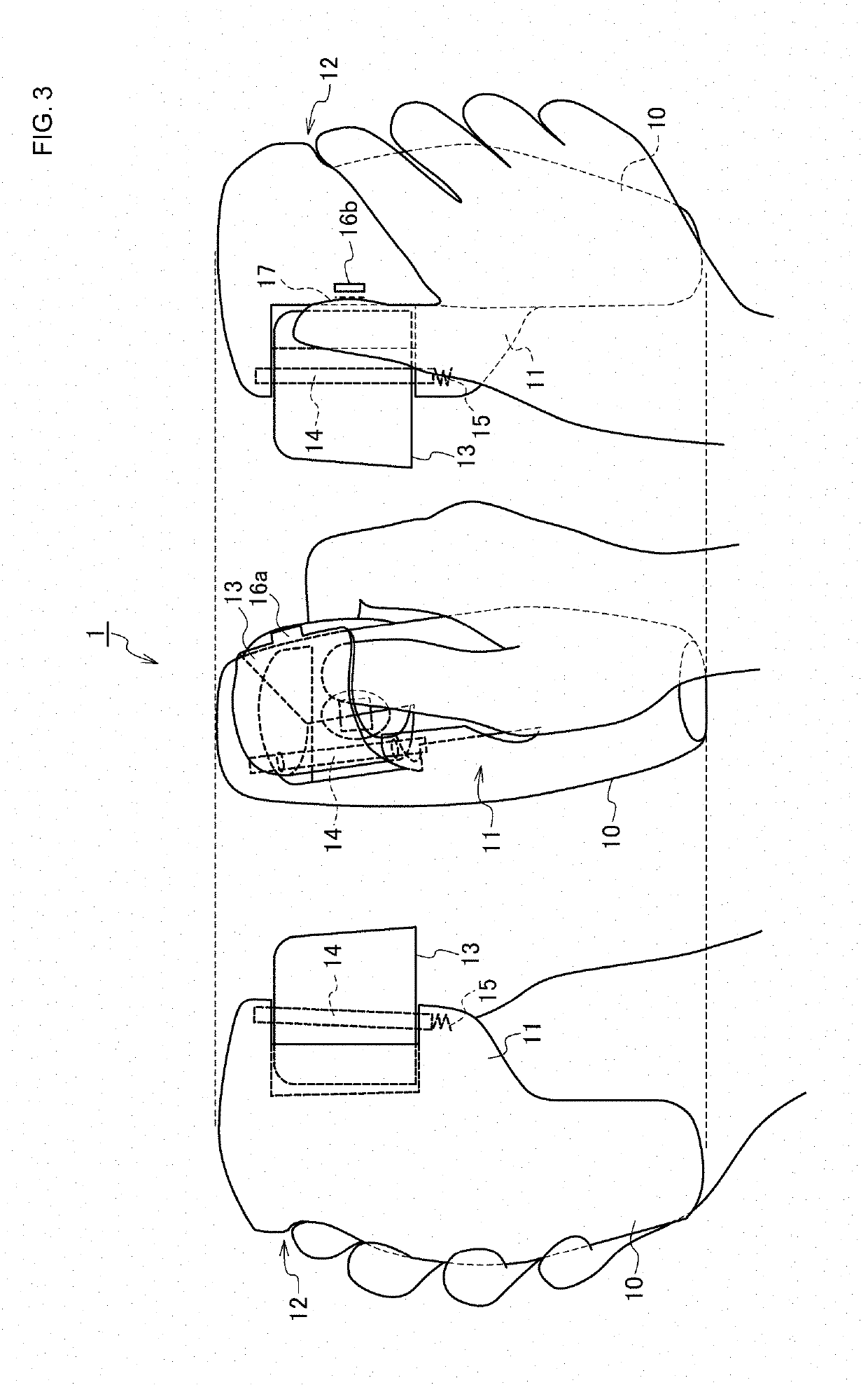
[0034]First, the configuration of a grip-type pulse wave measuring device 1 according to the exemplary embodiment will be described with reference to FIG. 1 to FIG. 6. FIG. 1 illustrates a front view and right and left side views for an appearance (a state in which a light shielding cover is closed) of the grip-type pulse wave measuring device 1 according to the embodiment, and FIG. 2 illustrates a front view and right and left side views for an appearance (a state in which the light shielding cover is opened) of the grip-type pulse wave measuring device 1. FIG. 3 is a view illustrating a state (a state before meas...


PUM


Abstract

A grip-type pulse wave measuring device includes a main body that has a substantially spheroid shape, and a stopper that projects along an axial direction of the main body and abuts against a side surface of a thumb to restrict a position of the thumb when a user grips the main body portion. Moreover, a light shielding cover is provided that is formed into a substantially semi-cylindrical shape and is mounted so as to be swingable about, as a swing shaft, a shaft that is provided in parallel to the axial direction of the main body. A photoplethysmographic sensor is disposed at a position offset from the swing shaft of the light shielding cover along a peripheral direction of the main body and is configured to acquire a photoplethysmographic signal.

Description

CROSS-REFERENCE TO RELATED APPLICATIONS[0001]The present application is a continuation of PCT / JP2017 / 033457 filed Sep. 15, 2017, which claims priority to Japanese Patent Application No. 2016-199557, filed Oct. 7, 2016, the entire contents of each of which are incorporated herein by reference.TECHNICAL FIELD[0002]The present disclosure relates to a grip-type pulse wave measuring device that acquires a pulse wave signal.BACKGROUND[0003]In recent years, there has been increasing people's interest in management, maintenance, and enhancement of health. It has been therefore desired that people can more easily obtain biological information such as pulse and electrocardiogram in everyday life. Patent Document 1 (identified below) discloses a pulse wave measuring device that measures pulse waves by causing a user to grip a main body portion and insert his / her index finger into a finger insertion portion. In addition, Patent Document 2 (also identified below) discloses a pulse wave detecting...

Claims


Application Information

Patent Timeline
IPC IPC(8): A61B5/021
CPCA61B5/02108A61B5/02141A61B5/02416A61B5/6826A61B2560/0425
Inventor SHIMUTA, TORU
Owner MURATA MFG CO LTD
Learn More