System for applying maximum driving efficiency point of load
a technology of driving efficiency and load, applied in the direction of dynamo-electric converter control, dynamo-electric brake control, dynamo-electric gear control, etc., can solve the problems of increased energy waste and unnecessary energy consumption, and achieve the effect of reducing energy to the maximum, reducing the amount of electric power used, and maximizing the operating efficiency poin
- Summary
- Abstract
- Description
- Claims
- Application Information
AI Technical Summary
Benefits of technology
Problems solved by technology
Method used
Image
Examples
first embodiment
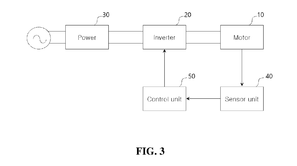
[0054]First, the configuration of the load maximum operating efficiency point application system for a load according to the present invention will be described with reference to FIG. 3.
[0055]As shown in FIG. 3, a system for applying maximum driving efficiency point of load according to the present invention, comprising, the motor 10 for driving the load, an inverter 20 for controlling the speed and the voltage of the motor 10, an a power supply unit 30 for receiving an AC commercial power supply and supplying power to the inverter 20, a sensor unit 40 for measuring the maintaining current and the maintaining current of the motor 10, and a control unit 50 for controlling the voltage and frequency (or speed) of the inverter 20 so as to have the maximum efficiency in consideration of the flow rate to be supplied and the maximum supply time.
[0056]The motor 10 is an induction motor that drives a load. For example, the load refers to a load such as an air conditioning fan or a pump that ...
second embodiment
[0106]Next, a configuration and a control method of a maximum operating efficiency point application system for a load according to the present invention will be described with reference to FIG. 6
[0107]The second embodiment of the present invention controls by the proportional power factor of the input current and the torque current in order to control the inverter instead of using the ROC of formula 5. Only the parts different from the first embodiment will be described below. For the unexplained part, the explanation of the first embodiment described above may be referenced.
[0108]First, in the second embodiment of the present invention, the sensor unit 40 is composed of current sensors for measuring the input current (I) and the torque current (Iq) in the motor 10.
[0109]Next, a method of controlling the inverter of the motor according to the second embodiment of the present invention will be described with reference to FIG. 6.
[0110]First, the speed N of the inverter 20 is determin...
third embodiment
[0117]Next, a configuration and a control method of a maximum operating efficiency point application system for a load according to the present invention will be described with reference to FIG. 7.
[0118]In a third embodiment of the present invention, the change amount of the total current after the voltage drop is additionally checked in the first embodiment, and the previous voltage is set as the final voltage when the total current increases. Only the parts different from the first embodiment will be described below. For the unexplained part, the explanation of the first embodiment described above may be referenced. As shown in FIG. 7, the speed N of the inverter 20 is first determined (S210), and an initial voltage corresponding to the set speed is set (S220). Next, the magnetic flux maintaining current (Id) and the torque current (Iq) of the motor 10 are measured (S230), and the rate of change (ROC) of the proportional amount of the torque current (Iq) to the magnetic flux maint...
PUM
 Abstract
Description
Claims
Application Information
 - R&D
- Intellectual Property
- Life Sciences
- Materials
- Tech Scout
- Unparalleled Data Quality
- Higher Quality Content
- 60% Fewer Hallucinations
Browse by: Latest US Patents, China's latest patents, Technical Efficacy Thesaurus, Application Domain, Technology Topic, Popular Technical Reports.
© 2025 PatSnap. All rights reserved.Legal|Privacy policy|Modern Slavery Act Transparency Statement|Sitemap|About US| Contact US: help@patsnap.com


