
Distributed and Decoupled Charging and Discharging Energy Storage System

Inactive Publication Date: 2019-07-04
GURIN MICHAEL H
View PDF3 Cites 3 Cited by
  • Summary
  • Abstract
  • Description
  • Claims
  • Application Information

AI Technical Summary

Benefits of technology

The invention aims to increase the daily cycles of charge / discharge to reduce the time required for financial return. It also aims to increase the value of each charge / discharge cycle by leveraging a charging co-product or byproduct, such as oxygen or carbon dioxide. The invention also manages the dispatch of charged energy storage for placement into an aggregate sustainable community flow battery electrolyte inventory to maximize the financial displacement of grid electricity. The invention also reduces transport costs by reducing the total volume requirements and avoids backup charges often included in utility rate structure when traditional power generation equipment is placed. The dynamic configuration of a vehicle transport is utilized for optimal volumetric efficiency and access effectiveness, particularly for autonomous or semi-autonomous vehicles. The invention further benefits from the mobilization of power consumer assets, particularly when these assets are solely direct current “DC” assets.

Problems solved by technology

Prior art includes the utilization of electric vehicles as a portion of a distributed grid yet does not obtain any secondary benefits or increase in utilization factors to lead to accelerated financial returns.
In fact, its operations of discharging at the second location requires the vehicle to not be utilized as a vehicle but rather solely a dispatched energy storage system, which is not economically particularly when the vehicle is autonomous or semi-autonomous as the bulk of the vehicle's asset cost is being dormant at such a time.

Method used


Image

  • Distributed and Decoupled Charging and Discharging Energy Storage System
  • Distributed and Decoupled Charging and Discharging Energy Storage System
  • Distributed and Decoupled Charging and Discharging Energy Storage System

Examples


Embodiment Construction

[0047]Here, as well as elsewhere in the specification and claims, individual numerical values and / or individual range limits can be combined to form non-disclosed ranges.

[0048]Exemplary embodiments of the present invention are provided, which reference the contained figures. Such embodiments are merely exemplary in nature. Regarding the figures, like reference numerals refer to like parts.

[0049]The invention significantly increases the daily cycles of charge / discharge in order to reduce the time duration required to achieve a financial return not only at the component level but most importantly at the system level.

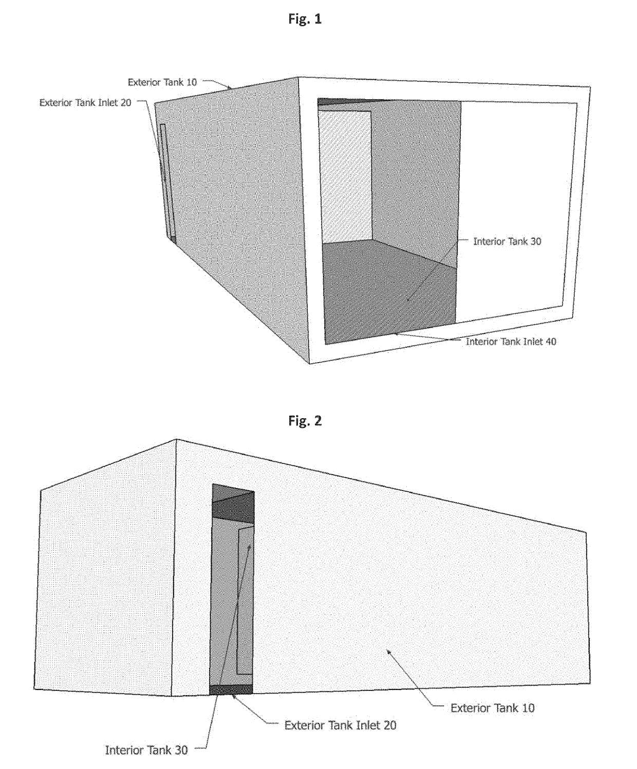
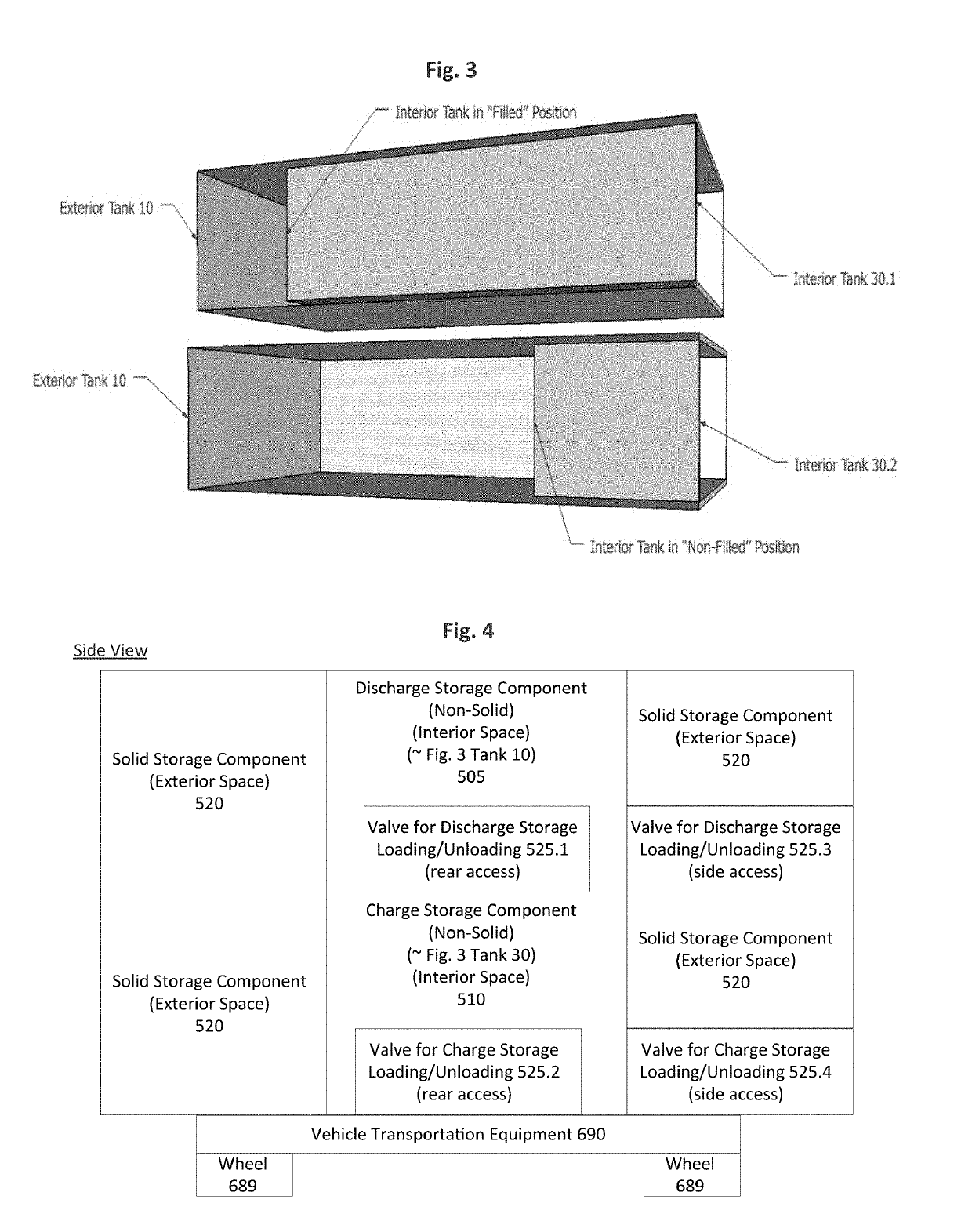
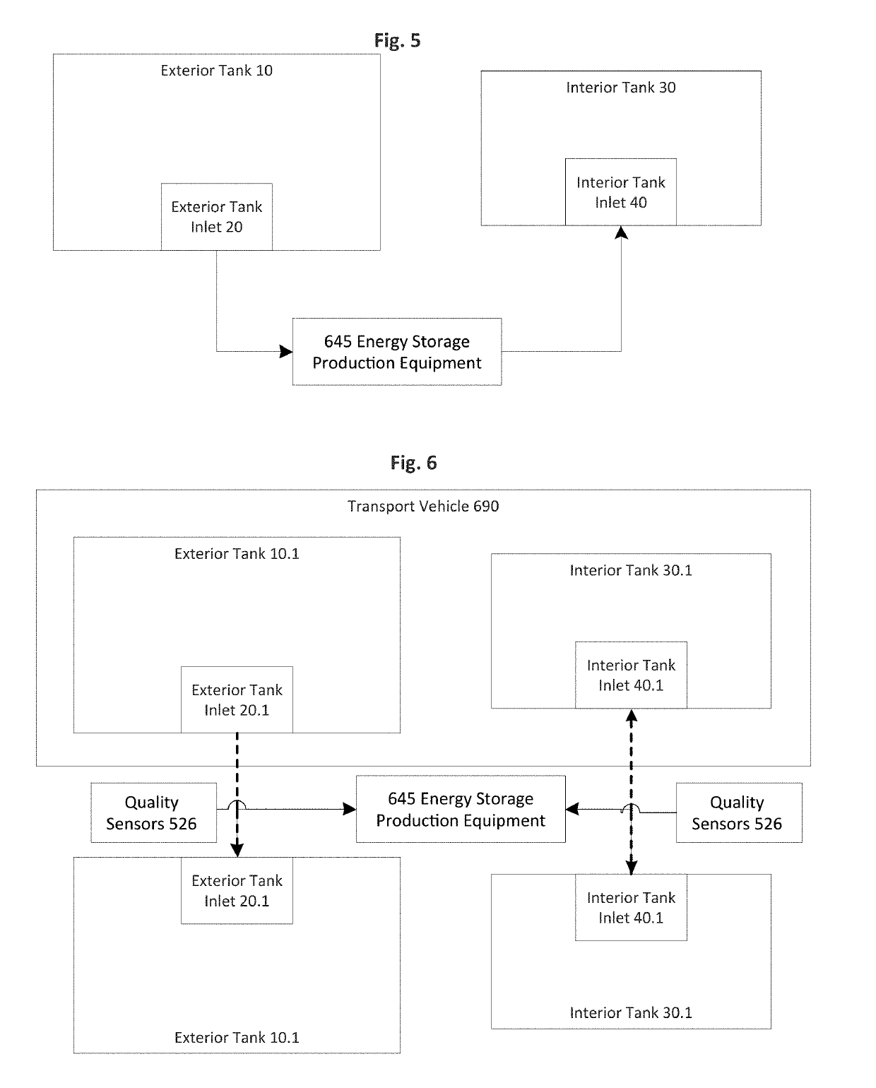
[0050]Turning to FIG. 1, FIG. 1 is an external view of the preferred tank-in-tank “T2” for the transport of the charged and discharged media. The preferred charged media has no adverse impact in the event of an accidental mixing of the charged with the discharged media. The exterior tank 10 has a fluid inlet shown as exterior tank inlet 20. And the interior tank 30 also ha...


PUM


Abstract

A system and method for energy distribution with decoupled by time and space domains that integrates energy storage capabilities that feature co-products utilization at the point of energy storage charging, byproduct utilization at the point of energy production, and time and space decoupling of vehicle shuttling energy storage media discharge to accelerate return on investment, reduce system energy consumption, and maximize utilization of existing energy infrastructure. Additionally, the system executes the energy transactions by controlling and integrating distributed energy producers and consumers with minimal grid dependence.

Description

FIELD OF INVENTION[0001]The present invention relates to an energy storage system having decoupled and distributed charging and discharging to at least two locations in which charging, and discharging are primarily separated with connectivity by a vehicle preferably utilizing a common and transferable energy storage medium or charging co-product or byproduct to increase the utilization rate of both the vehicle and energy storage to accelerate financial and economic returns.BACKGROUND OF INVENTION[0002]Prior art includes the utilization of electric vehicles as a portion of a distributed grid yet does not obtain any secondary benefits or increase in utilization factors to lead to accelerated financial returns. This embodiment solely bypasses the transmission lines of the traditional grid. In fact, its operations of discharging at the second location requires the vehicle to not be utilized as a vehicle but rather solely a dispatched energy storage system, which is not economically part...

Claims


Application Information

Patent Timeline
IPC IPC(8): B60L11/18H02J7/00
CPCH02J7/0068B60Y2300/91Y10S903/907B60L53/00B60Y2200/92B60K6/28B60L58/12B60Y2200/91B60L53/665B60L53/65B60L53/64H02J2310/48Y02T90/167Y02T10/70Y02T90/14Y02T10/7072Y02T90/12Y04S30/14
Inventor GURIN, MICHAEL H.
Owner GURIN MICHAEL H
Learn More