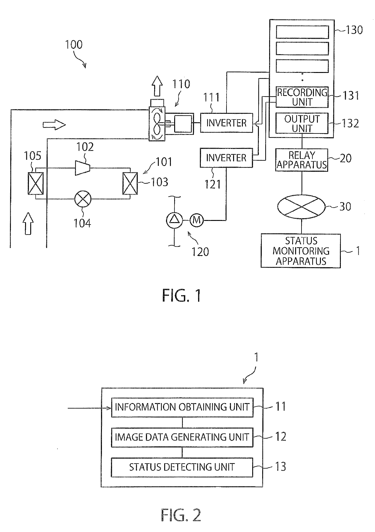
Status monitoring apparatus, status monitoring method, and program
- Summary
- Abstract
- Description
- Claims
- Application Information
AI Technical Summary
Benefits of technology
Problems solved by technology
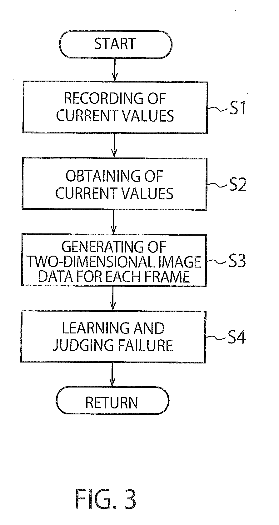
Method used
Image

Examples
modification example 1
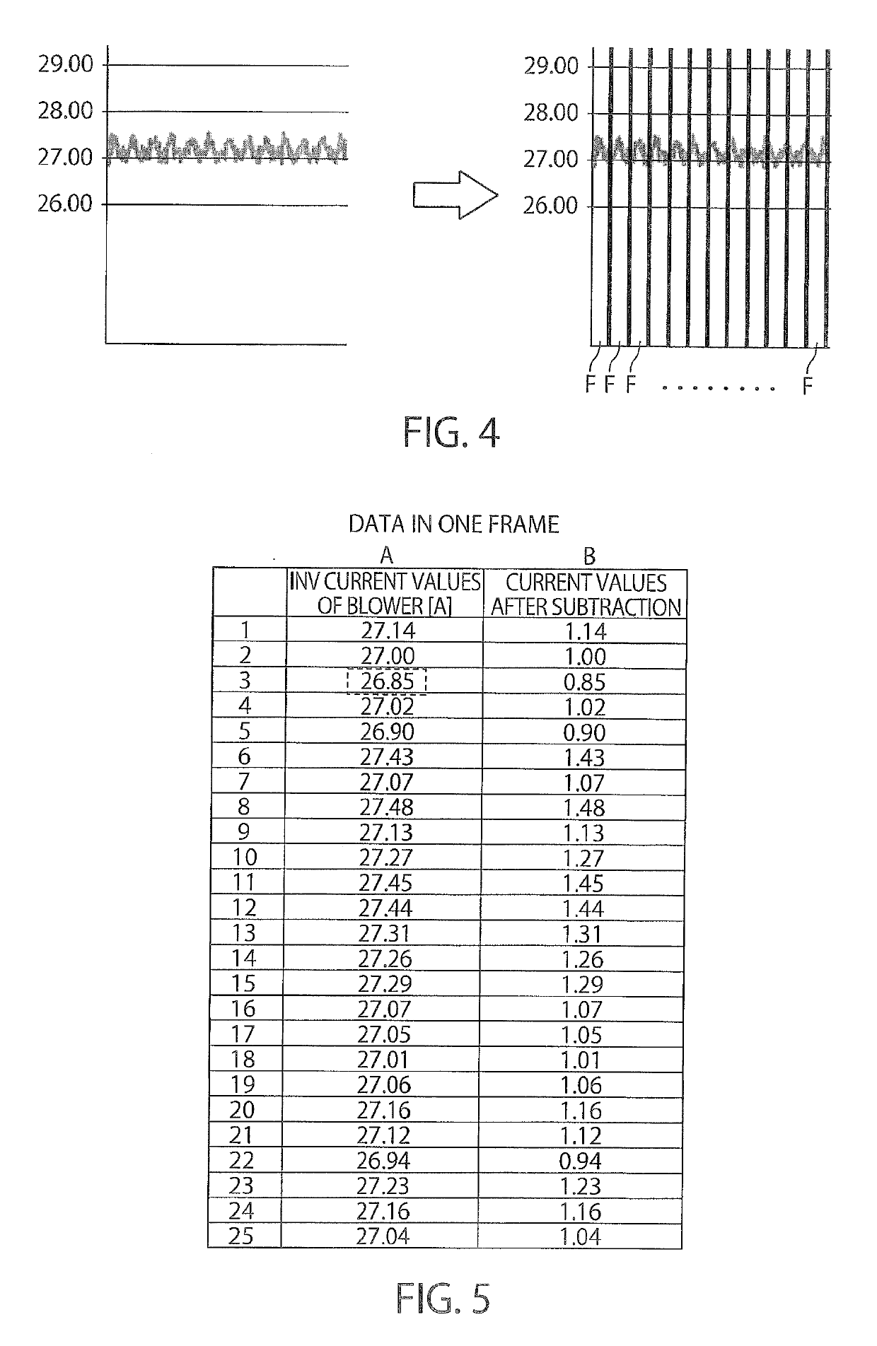
[0043]Next, a modification example 1 is described. The modification example 1 differs from the aforementioned embodiment in the process of the image data generating unit 12. The image data generating unit 12 according to the modification example 1 firstly partitions detected information items (current values) by two frames F continuously adjacent to each other, sequentially shifts a first frame F of the two frames F at detection intervals of detected information items, until the first frame F is positioned to overlap with a next frame F, extracts maximum values and minimum values of the detected information items at a position before the frame is shifted and at respective positions after the frame is shifted. Then, the image data generating unit 12 chronologically arranges, in the first frame, the extracted maximum values and the minimum values in an ascending order of the detection timings. Then, the image data generating unit 12 generates image data showing areas like strips such ...
modification example 2
[0046]Next, a modification example 2 is described. The modification example 2 differs from the aforementioned embodiment in the process of the image data generating unit 12. FIG. 8 is a view for conceptually explaining an image data generating step according to the modification example 2. In view of FIG. 8, the image data generating unit 12 according to the modification example 2 partitions detected information items (current values) by two frames F, F continuously adjacent to each other, and extracts, in the respective frames F, F, maximum values Max(1), Max(2) and minimum values Min(1), Min(2) of the detected information items. Then, the image data generating unit 12 sets the maximum value Max(1) and the minimum value Min(1) of the detected information items of the first frame F of the adjacent frames F, F, at a front end of the axis of abscissa of the first frame F. In addition, the image data generating unit 12 sets the maximum value Max(2) and the minimum value Min(2) of the de...
PUM
 Abstract
Description
Claims
Application Information
 - R&D
- Intellectual Property
- Life Sciences
- Materials
- Tech Scout
- Unparalleled Data Quality
- Higher Quality Content
- 60% Fewer Hallucinations
Browse by: Latest US Patents, China's latest patents, Technical Efficacy Thesaurus, Application Domain, Technology Topic, Popular Technical Reports.
© 2025 PatSnap. All rights reserved.Legal|Privacy policy|Modern Slavery Act Transparency Statement|Sitemap|About US| Contact US: help@patsnap.com