
Exhaust gas sampling apparatus, exhaust gas analysis system, exhaust gas sampling method, and exhaust gas sampling program

a technology of exhaust gas sampling and exhaust gas, applied in the direction of instruments, machines/engines, volume/mass flow by differential pressure, etc., can solve the problems of reducing the s/n ratio at the time of analyzing the sampled exhaust gas, reducing the analysis accuracy, and reducing the amount of sampling bags

Active Publication Date: 2019-06-27
HORIBA LTD
View PDF5 Cites 2 Cited by
  • Summary
  • Abstract
  • Description
  • Claims
  • Application Information

AI Technical Summary

Benefits of technology

The present invention is a device that can accurately analyze the exhaust gas of a hybrid vehicle engine. It can also be used for a test that involves collecting exhaust gas into a sampling bag over a specific period of time.

Problems solved by technology

As a result, an S / N ratio at the time of analyzing the sampled exhaust gas decreases to reduce analysis accuracy.
However, since the method as described above stops the sampling into the sample bag when the engine is stopped, a sampling amount in the sampling bag decreases, and therefore there occurs a problem that on occasions such as when introducing sampled exhaust gas into, for example, various analyzers, the amount of the exhaust gas is insufficient.
Further, the sampling into the sampling bag is stopped when the engine is switched from an operation state to a stop state, and therefore the exhaust gas remains in a flow path and the like constituting a CVS apparatus, thus possibly causing a measurement error.
In addition, some test may prescribe the continuation of sampling into a sampling bag over a predetermined sampling time (e.g., 505 seconds) at, for example, a flow rate proportional to a main flow rate of a CVS apparatus, and for such a test, the above method cannot be employed.

Method used


Image

  • Exhaust gas sampling apparatus, exhaust gas analysis system, exhaust gas sampling method, and exhaust gas sampling program
  • Exhaust gas sampling apparatus, exhaust gas analysis system, exhaust gas sampling method, and exhaust gas sampling program
  • Exhaust gas sampling apparatus, exhaust gas analysis system, exhaust gas sampling method, and exhaust gas sampling program

Examples


Embodiment Construction

[0037]In the following, one embodiment of the exhaust gas analysis system according to the present invention will be described with reference to drawings.

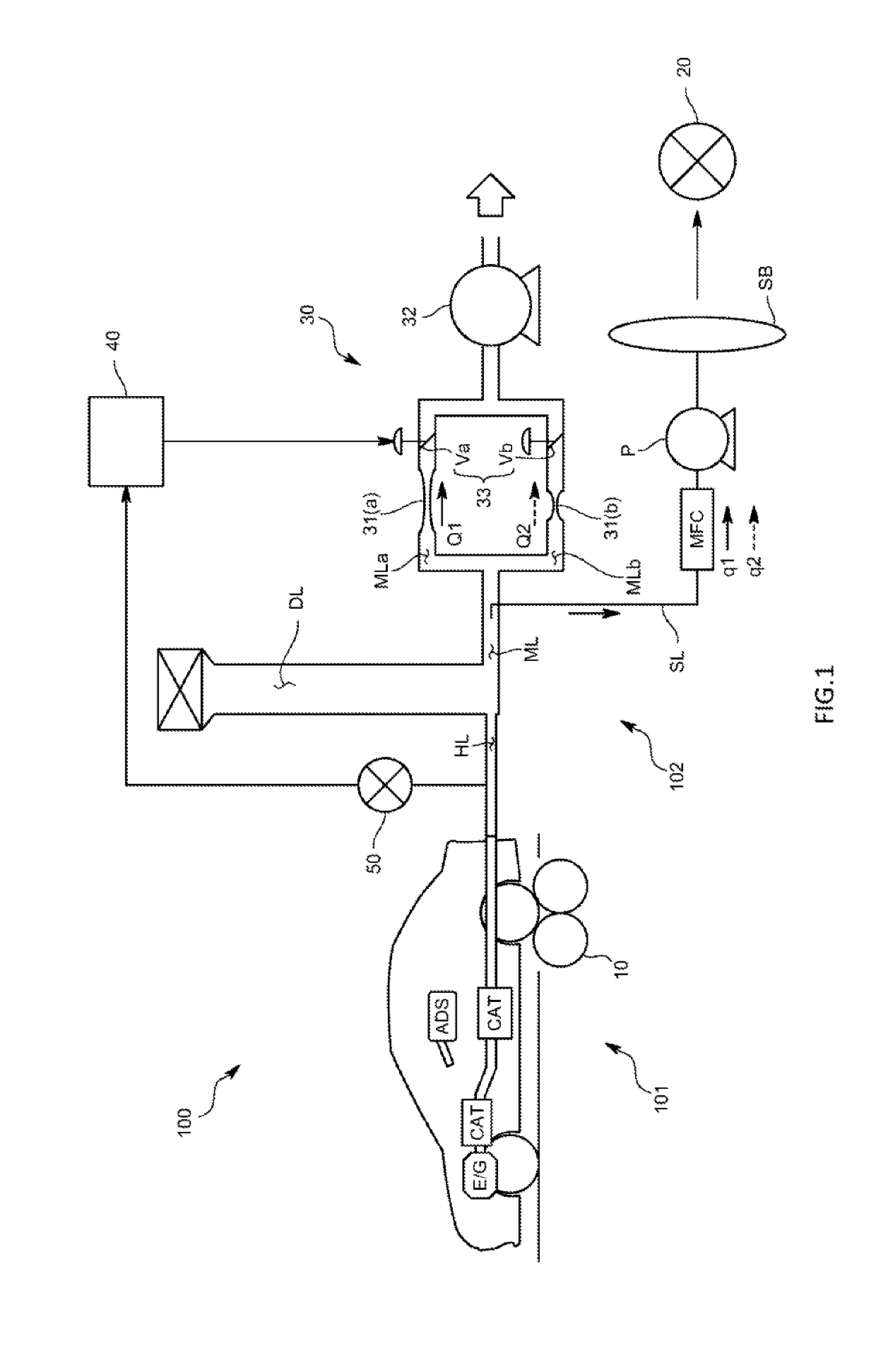
[0038]An exhaust gas analysis system 100 of the present embodiment is one that is used to perform component analysis of exhaust gas discharged from an engine of a hybrid vehicle having the engine and an electric motor (motor) as a test vehicle such as HEV or PHEV, fuel consumption measurement, and the like, and of a dilution sampling type that dilutes the exhaust gas with diluent gas to perform concentration measurement. Note that the exhaust gas analysis system 100 may be one of a direct sampling type that samples the exhaust gas discharged from the engine without diluting the exhaust gas. Also, a test target is not limited to a finished vehicle, but may be a drive train having an engine and an electric motor (motor).

[0039]Specifically, as illustrated in FIG. 1, the exhaust gas analysis system 100 includes: a chassis dynamometer 1...


PUM


Abstract

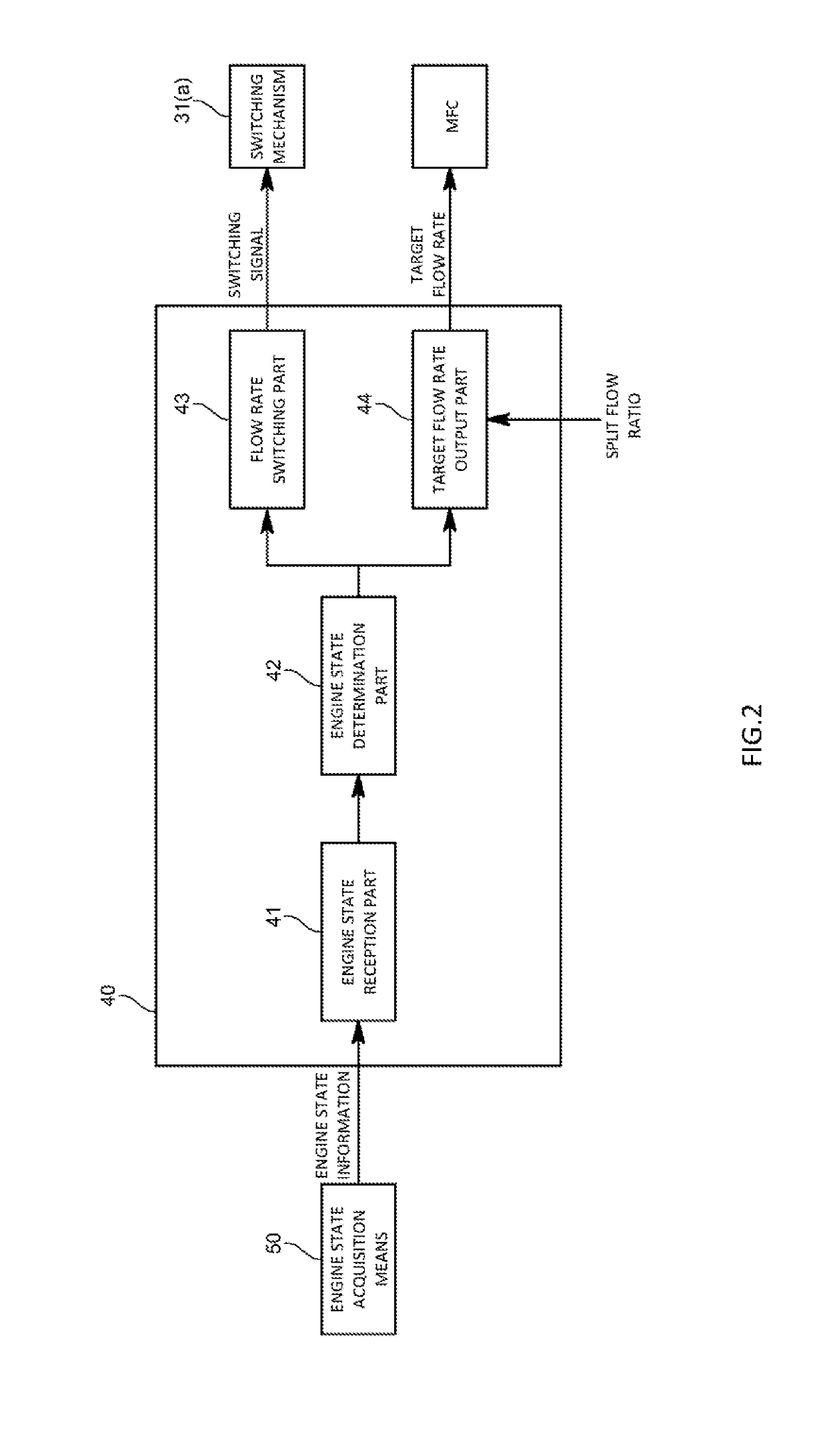
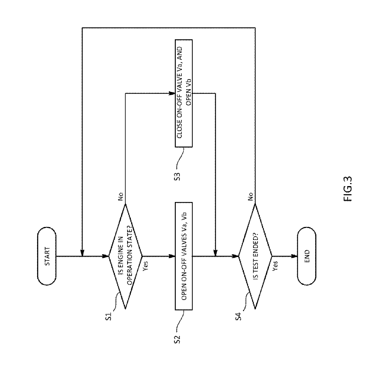
To provide an exhaust gas analysis system that can accurately analyze exhaust gas discharged from an engine of a hybrid vehicle and can also be applied to a test that continues sampling into a sampling bag over a predetermined sampling time, a sampling apparatus is adapted to include a main flow path through which the exhaust gas flows, a sampling flow path that is connected to the main flow path to sample the exhaust gas into a sampling bag, and a constant flow rate mechanism that is provided in the main flow path and configured to be able to change a main flow rate that is an exhaust gas flow rate through the main flow path. Additionally, a control device is adapted to control the constant flow rate mechanism to change the main flow rate and change a sampling flow rate that is an exhaust gas flow rate through the sampling flow path.

Description

TECHNICAL FIELD[0001]The present invention relates to an exhaust gas sampling apparatus, an exhaust gas analysis system, an exhaust gas sampling method, and an exhaust gas sampling program.BACKGROUND ART[0002]As this sort of exhaust gas analysis system, there is one including a constant volume sampling apparatus (hereinafter also referred to as a CVS apparatus) that controls mixed gas produced by mixing diluent gas in exhaust gas discharged from an engine to have a constant flow rate, and samples the mixed gas into a sampling bag.[0003]When analyzing exhaust gas from a hybrid vehicle (HEV or PHEV) using the CVS apparatus, if even at the time of stopping an engine, mixed gas continues to be sampled into the sampling bag in the same manner as at the time of operating the engine, only the diluent gas is sampled at the time of stopping the engine, and therefore the exhaust gas in the sampling bag is diluted. As a result, an S / N ratio at the time of analyzing the sampled exhaust gas decr...

Claims


Application Information

Patent Timeline
IPC IPC(8): F01N11/00G01N1/22
CPCF01N11/007G01N1/2252G01N1/2247G01N33/0004G01F1/44G01F1/76G01N2001/2255
Inventor TSURUMI, KAZUYA
Owner HORIBA LTD
Learn More