
Dialysis wall box apparatus and wall chase system

a technology of dialysis and box apparatus, which is applied in water installations, construction, building components, etc., can solve the problems of increasing the real estate and construction capital cost of building structures, increasing the need for disinfection and maintenance, and occupying substantial floor space in treatment facilities, so as to reduce the amount of facility floor space and room volume, compact and effective, and reduce the effect of joints

Active Publication Date: 2019-06-20
TAWEH GEORGE
View PDF3 Cites 2 Cited by
  • Summary
  • Abstract
  • Description
  • Claims
  • Application Information

AI Technical Summary

Benefits of technology

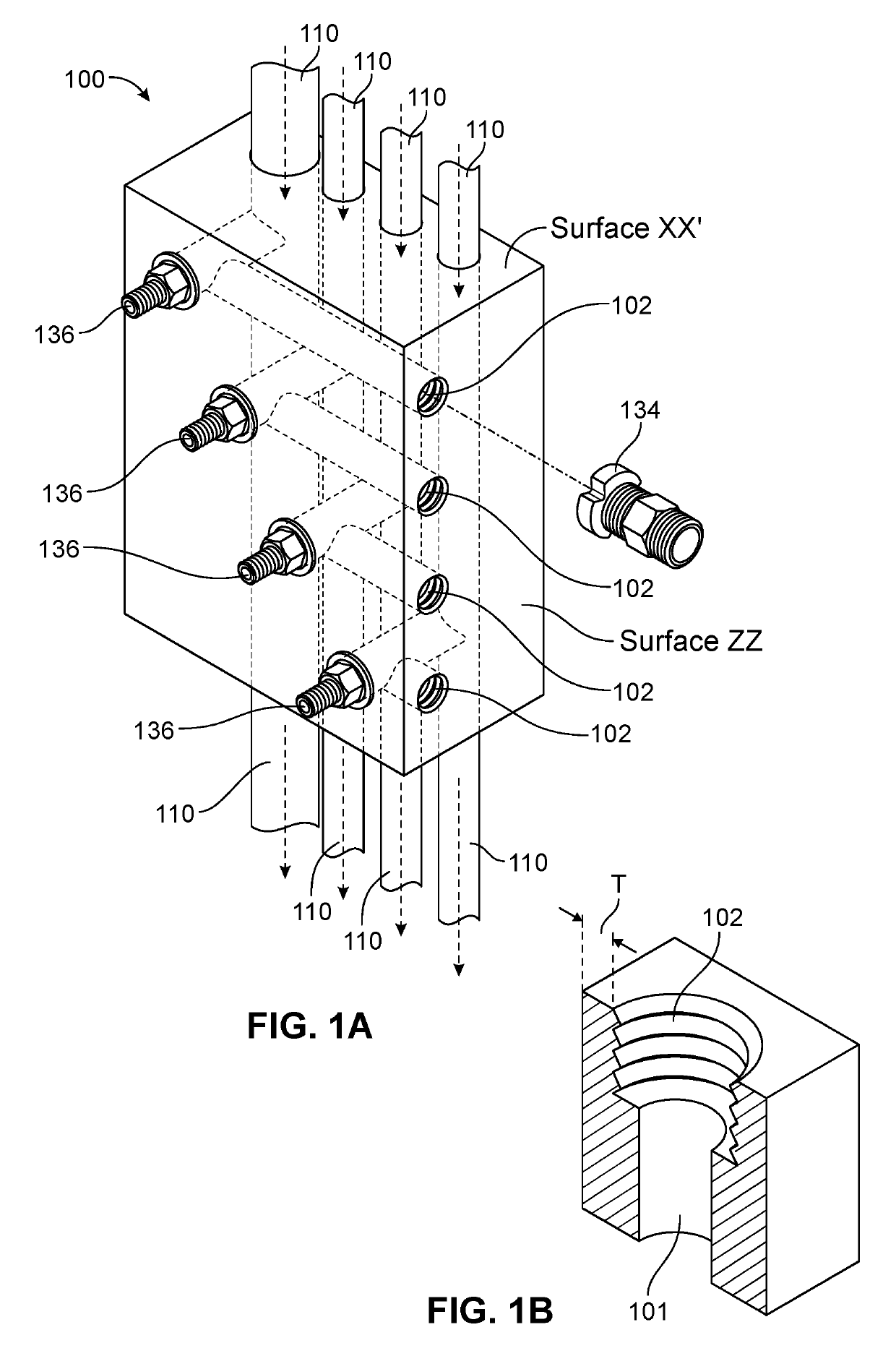
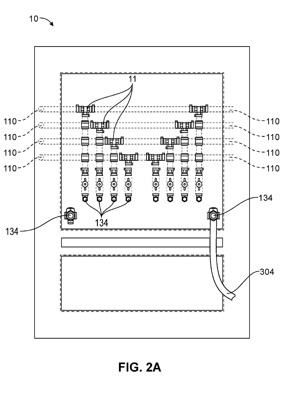
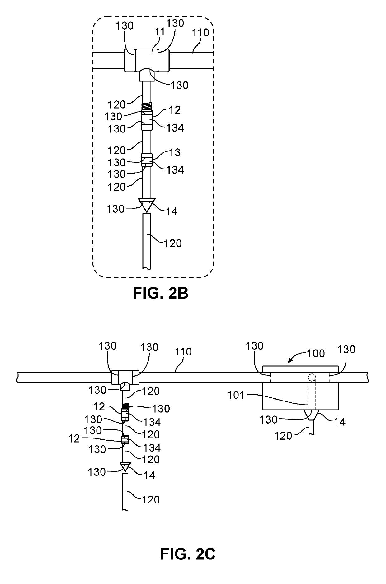
The present invention provides a wall box that is integrated and more effective in managing disinfection and minimizing bacterial growth and plumbing leaks. The wall box is made of fluid flow conduits and connecting ports that reduce the number of plumbing line connection joints. It is also compatible with contemporary kidney-dialysis treatment facilities' piping materials (e.g. PEX) to maintain sterility of the treatment facility's plumbing system. The wall box can be constructed at a smaller footprint compared to prior art wall boxes while still maintaining fluid pressure containment requirements. Additionally, the present invention provides a separate waste collector for receiving kidney-dialysis machine fluid wastes, a drain line for directing such wastes away from the building structure, and a wall chase system that eliminates the need for additional fittings and reduces the space requirements for a wall box. The present invention also includes a fluid funnel means for capturing fluid leaks and channeling them directly to a treatment facility's drain line. The invention provides a more compact and effective solution for managing disinfection and maintaining sterility in kidney-dialysis treatment facilities.

Problems solved by technology

Such chase systems require substantial treatment facility floor space and, as such, increase real estate and construction capital costs of building structures utilizing them.
The more such joints are created, the greater the chance of fluid leaks and bacterial growth, thereby resulting in an increased need for disinfection and maintenance.
Marinan further discloses that it is well established that such leakages promote the development of mold, may produce other health risks associated with the presence of persistent moisture, and can cause costly damage to the affected building components.

Method used


Image

  • Dialysis wall box apparatus and wall chase system
  • Dialysis wall box apparatus and wall chase system
  • Dialysis wall box apparatus and wall chase system

Examples


Embodiment Construction

[0016]Reference will now be made in detail to specific embodiments or features, examples of which are illustrated in the accompanying drawings. Wherever possible, corresponding or similar reference numbers will be used throughout the drawings to refer to the same or corresponding parts. Moreover, references to various elements described herein, are made individually or collectively when there may be more than one element of the same type. However, such references are merely exemplary in nature. It may be noted that any reference to elements in the singular may also be construed to relate to the plural and vice-versa without limiting the scope of the disclosure to the exact number or type of such elements unless set forth explicitly in the appended claims.

[0017]FIG. 1A illustrates an embodiment of the present invention wall box 100. The exemplary wall box 100 is a fluid transport housing generally constructed of PVC (polyvinyl chloride) or PEX (crosslinked polyethylene) material, and...


PUM


Abstract

A wall box apparatus and building wall chase system is described. A wall box apparatus is configured to operatively reduce the number of fluid line joints connected to building and machinery plumbing lines, and more particularly to dialysis treatment facilities and kidney-dialysis machines, respectively. A space-saving wall chase system is configured using the wall box to connect plumbing lines in a dialysis treatment facility to dialysis machines.

Description

BACKGROUND OF THE INVENTION[0001]This invention relates to providing an improved building wall chase system and a wall box apparatus for routing and connecting to, respectively, plumbing lines within the interior of a new or existing building structure and machines within the building. More particularly, this invention relates to providing a wall chase system and wall box apparatus within the interior of a specialty medical treatment facility (e.g., kidney-dialysis treatment facility).[0002]Contemporary kidney-dialysis treatment facilities include groupings of multiple kidney-dialysis machines located at a designated station within a common treatment room. Each station includes a kidney-dialysis machine configured to receive treated water (e.g., Reverse Osmosis (RO) or Deionized (DI) water), acid concentrates, and bicarbonate concentrates dialysate, electrical power, etc., and waste-fluid disposal via a wall-box and wall chase system. Contemporary wall-boxes such as those manufactur...

Claims


Application Information

Patent Timeline
IPC IPC(8): E03C1/02
CPCE03C1/021E03C1/025A61M1/14E04C2/521A61M2209/084A61M1/1656A61M39/105A61M1/1657
Inventor TAWEH, GEORGE
Owner TAWEH GEORGE
Learn More