Antenna and wireless module

a wireless module and antenna technology, applied in the field of antennas, can solve the problems of unfavorable downsizing and the inability to configure the whole antenna on one substrate, and achieve the effect of small and highly convenient wireless modules

Active Publication Date: 2019-05-23
MURATA MFG CO LTD
View PDF4 Cites 0 Cited by
  • Summary
  • Abstract
  • Description
  • Claims
  • Application Information

AI Technical Summary

Benefits of technology

[0012]With this configuration, the directivity corresponding to antenna gain caused by the first conductive foil is controlled by using the second conductive foil, and thereby the gain of the antenna can achieve unidirectionality. Since the grounded conductive foil, the first conductive foil, and the second conductive foil are all disposed on one substrate, the antenna can be configured in a planar area of the substrate, the planar area having a thickness not substantially exceeding the thickness of the substrate. In addition, the antenna together with various circuits such as a communication circuit is easily mounted on the substrate. In particular, the first conductive foil and the second conductive foil each have the one end that is supplied with power and that is grounded and the other end that is open and thus operate as a monopole antenna. Accordingly, the first conductive foil and the second conductive foil can be configured in an area for a ¼ wave length. This provides a unidirectional antenna enabled to be configured on one substrate thinly and in a small size. The grounded conductive foil may also serve as a grounded conductive foil for power supply. In this case, the area occupied by the antenna is reduced, and the reduction further contributes to downsizing of a set.
[0018]With this configuration, the grounded conductive foil causes the formation of the mirror images of the first conductive foil and the second conductive foil, and the gain of the antenna is thereby enhanced.
[0024]With this configuration, the communication circuit and the above-described antenna are disposed on one substrate, and thereby a small and highly convenient wireless module is provided.

Problems solved by technology

However, the antenna in Patent Document 1 has a three-dimensional structure in which the dielectric substrate is provided upright on the ground plate, and thus the whole of the antenna cannot be configured on one substrate.
The antenna in Non Patent Document 1 has the radiating element serving as the dipole antenna, thus needs an area for a half wavelength, and is unfavorable for downsizing.

Method used


Image

  • Antenna and wireless module
  • Antenna and wireless module
  • Antenna and wireless module

Examples


embodiment 1

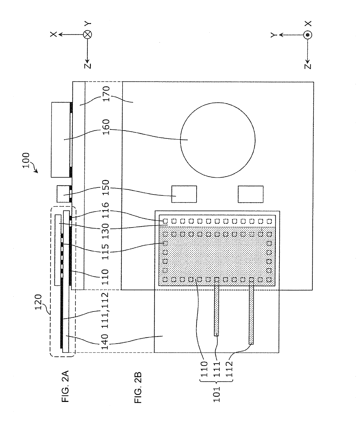
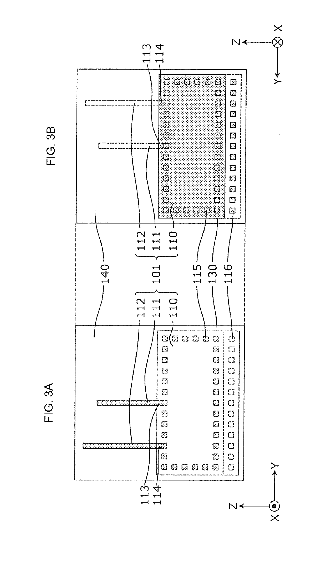
[0038]An antenna according to Embodiment 1 is a unidirectional antenna including conductive foils in predetermined patterns on a substrate. The substrate is provided with various circuits including a communication circuit, together with the antenna, and a wireless module is configured by using the components. The wireless module is used in a communication device such as a radio beacon.

[0039]Note that the radio beacon is a near-field device that wirelessly provides information. The radio beacon has been increasingly widely used in recent years and provides, for example, information regarding an installation location and information regarding a product placed in the installation location to a communication instrument nearby by using radio signals. The characteristics of the radio beacon might lead to a desire to limit the radiation of the radio signals to a specific direction (that is, a desire to have the antenna gain corresponding to unidirectionality). The antenna according to Embo...

embodiment 2

[0075]An antenna according to Embodiment 2 is a unidirectional antenna including conductive foils on a substrate in predetermined patterns, like the antenna according to Embodiment 1. The antenna according to Embodiment 2 is different from the antenna according to Embodiment 1 in that the antenna according to Embodiment 2 is formed on the set substrate, instead of the module substrate and is also different in the details of the shapes of conductive foils included in the antenna. Hereinafter, the components described in Embodiment 1 are denoted by the same reference numerals, and description thereof is omitted. Matters different from those in Embodiment 1 will mainly be described.

[0076]FIG. 8 is a block diagram illustrating an example functional configuration of a communication device including the antenna according to Embodiment 2. As illustrated in FIG. 8, a communication device 200 includes an antenna 201, a wireless module 220 including the circuit unit 130, and the battery 160. ...


PUM


Abstract

An antenna (101) includes a grounded conductive foil (110) disposed on a module substrate (140), a first conductive foil (111), and a second conductive foil (112). The first conductive foil (111) and the second conductive foil (112) are disposed on the module substrate (140), are elongated, and do not overlap with the grounded conductive foil (110) in a plan view of the module substrate (140). The first conductive foil (111) has one end supplied with an antenna signal and the other end that is open. The second conductive foil (112) has one end connected to the grounded conductive foil (110) and the other end that is open. A wireless module (120) includes a circuit unit (130) including a communication circuit and provided to the module substrate (140) on which the antenna (101) is formed.

Description

[0001]This is a continuation of International Application No. PCT / JP2017 / 026932 filed on Jul. 25, 2017 which claims priority from Japanese Patent Application No. 2016-146719 filed on Jul. 26, 2016. The contents of these applications are incorporated herein by reference in their entireties.BACKGROUND OF THE DISCLOSUREField of the Disclosure[0002]The present disclosure relates to an antenna and particularly relates to a unidirectional antenna configured on a substrate.Description of the Related Art[0003]To date, antennas including conductive foils on a substrate such as a printed circuit board or a ceramic multi-layer substrate have been widely used.[0004]For example, Patent Document 1 discloses an array antenna including a dielectric substrate on which conductive foils are disposed as a feed element and parasitic elements and that is provided upright on the ground plate. According to the array antenna, the conductive foils having predetermined lengths and disposed at a predetermined ...

Claims


Application Information

Patent Timeline
Patent Type & Authority Applications(United States)
IPC IPC(8): H01Q23/00H01Q9/04H01Q5/335H01Q25/04
CPCH01Q23/00H01Q9/0407H01Q5/335H01Q25/04H01Q1/38H01Q1/48H01Q19/30H01Q5/328
Inventor ITO, YUICHIIZAWA, MASAHIROKOBAYASHI, MASAYUKIAMACHI, NOBUMITSU
Owner MURATA MFG CO LTD
Why Eureka
Try Eureka