
Graphical user interface for displaying automatically segmented individual parts of anatomy in a surgical navigation system

a navigation system and user interface technology, applied in the field of graphical user interfaces for surgical navigation systems, can solve the problems of restricting the communication of surgeons and navigation systems, and achieve the effect of facilitating identification utilizing image segmentation and increasing planning accuracy

Active Publication Date: 2019-05-16
AUGMEDICS INC
View PDF0 Cites 68 Cited by
  • Summary
  • Abstract
  • Description
  • Claims
  • Application Information

AI Technical Summary

Benefits of technology

[0005]Incorporating image segmentation processes that automatically identify various bone landmarks, based on their density, can increase planning accuracy. One such bone landmark is the spinal pedicle, which is made up of dense cortical bone making its identification utilizing image segmentation easier. The pedicle is used as an anchor point for various types of medical implants. Achieving proper implant placement in the pedicle is heavily dependent on the trajectory selected for implant placement. Ideal trajectory is identified by surgeon based on review of advanced imaging (e.g., CT or MRI), goals of the surgical procedure, bone density, presence or absence of deformity, anomaly, prior surgery, and other factors. The surgeon then selects the appropriate trajectory for each spinal level. Proper trajectory generally involves placing an appropriately sized implant in the center of a pedicle. Ideal trajectories are also critical for placement of inter-vertebral biomechanical devices.
[0006]Another example is placement of electrodes in the thalamus for the treatment of functional disorders, such as Parkinson's. The most important determinant of success in patients undergoing deep brain stimulation surgery is the optimal placement of the electrode. Proper trajectory is defined based on preoperative imaging (such as MRI or CT) and allows for proper electrode positioning.

Problems solved by technology

The fundamental limitation of surgical navigation systems is that they provide restricted means of communicating to the surgeon.
Currently-available navigation systems present some drawbacks.

Method used


Image

  • Graphical user interface for displaying automatically segmented individual parts of anatomy in a surgical navigation system
  • Graphical user interface for displaying automatically segmented individual parts of anatomy in a surgical navigation system
  • Graphical user interface for displaying automatically segmented individual parts of anatomy in a surgical navigation system

Examples


Embodiment Construction

[0096]The following detailed description is of the best currently contemplated modes of carrying out the invention. The description is not to be taken in a limiting sense, but is made merely for the purpose of illustrating the general principles of the invention.

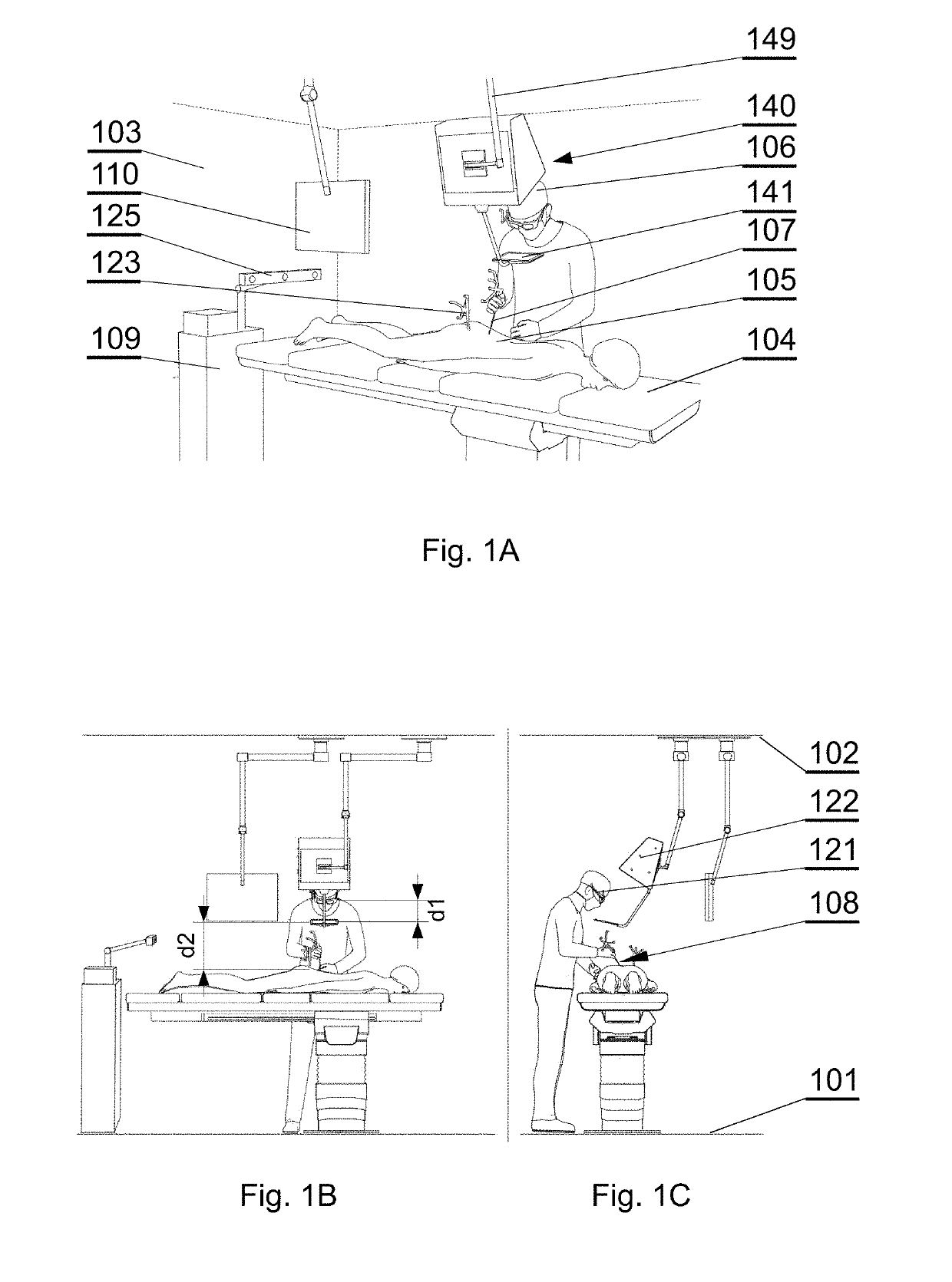
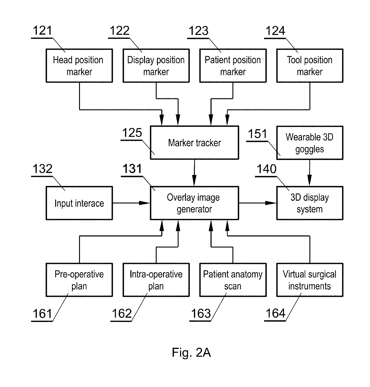
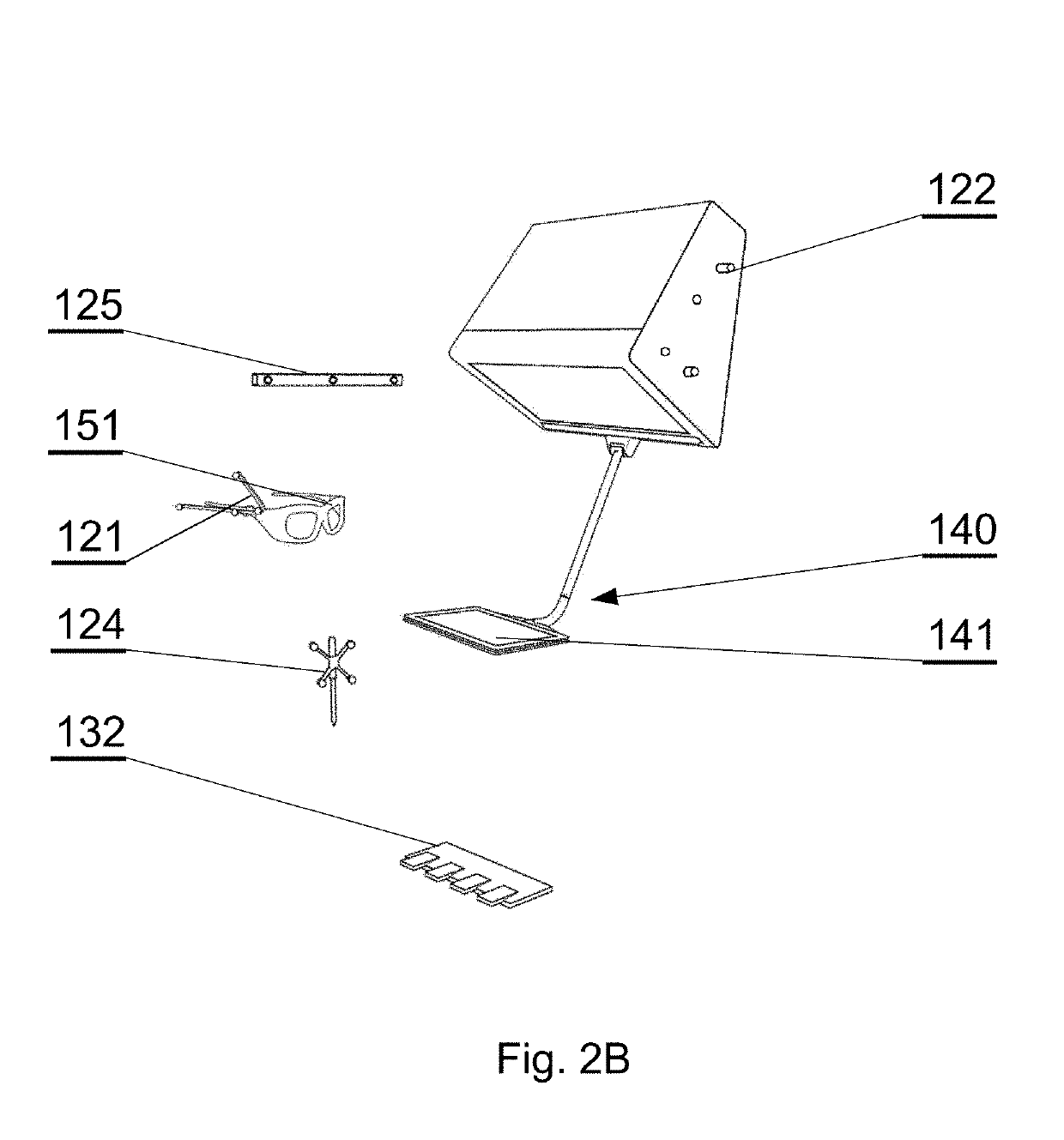
[0097]The system presented herein, in accordance with one embodiment, comprises a 3D display system 140 to be implemented directly on real surgical applications in a surgical room as shown in FIGS. 1A-1C. The 3D display system 140 as shown in the embodiment of FIGS. 1A-1C comprises a 3D display 142 for emitting a surgical navigation image 142A towards a see-through mirror 141 that is partially transparent and partially reflective, such that an augmented reality image 141A collocated with the patient anatomy in the surgical field 108 underneath the see-through mirror 141 is visible to a viewer looking from above the see-through mirror 141 towards the surgical field 108.

[0098]The surgical room typically comprises a floor 101 o...


PUM


Abstract

A surgical navigation system includes a source of a patient anatomy data, wherein the patient anatomy data comprises a three-dimensional reconstruction of a segmented model comprising at least two sections representing parts of the anatomy. A surgical navigation image generator is configured to generate a surgical navigation image comprising the patient anatomy. A 3D display system is configured to show the surgical navigation image wherein the display of the patient anatomy is selectively configurable such that at least one section of the anatomy is displayed and at least one other section of the anatomy is not displayed.

Description

TECHNICAL FIELD[0001]The present disclosure relates to graphical user interfaces for surgical navigation systems, in particular to a system and method for operative planning and real time execution of a surgical procedure including displaying automatically segmented individual parts of the patient anatomy.BACKGROUND[0002]Some of typical functions of a computer-assisted surgery (CAS) system with navigation include presurgical planning of a procedure and presenting preoperative diagnostic information and images in useful formats. The CAS system presents status information about a procedure as it takes place in real time, displaying the preoperative plan along with intraoperative data. The CAS system may be used for procedures in traditional operating rooms, interventional radiology suites, mobile operating rooms or outpatient clinics. The procedure may be any medical procedure, whether surgical or non-surgical.[0003]Surgical navigation systems are used to display the position and orie...

Claims


Application Information

Patent Timeline
Patent Type & Authority Applications(United States)
IPC IPC(8): A61B34/10G06F3/01G06T19/00G06T7/11G06T5/00A61B5/00A61B34/20A61B90/00
CPCA61B34/10G06F3/012G06T19/006G06T7/11G06T5/002A61B5/7267A61B34/20A61B90/37G06T2207/20084G06T2207/20081G06K9/6257G06K2209/055G06T2207/30012G06T7/20G06T2207/30208G06F3/013G06T2207/10081G06T2219/004A61B2034/105A61B2090/367A61B2090/502G02B2027/0134G02B2027/0136A61B2034/107A61B2090/3618A61B2090/372A61B2090/363A61B2090/365A61B2090/368G02B27/017G02B2027/0138G02B2027/0187A61B90/36A61B2034/102A61B2034/2055A61B34/25A61B2090/3983A61B2090/3762A61B2017/00216G02B27/0172A61B2034/2068G02B2027/0196G02B2027/0178G06V2201/033G06F18/2148A61B2034/2063A61B34/30
Inventor SIEMIONOW, KRIS B.LUCIANO, CRISTIAN J.MEJIA OROZCO, EDWING ISAAC
Owner AUGMEDICS INC
Learn More