Method and device for determining movement trajectory, mobile robot and storage medium
A technology for mobile robots and moving trajectories, which is applied in instruments, image analysis, image enhancement, etc., and can solve problems such as low accuracy of moving trajectories and the inability of mobile robots to safely pass through narrow passages
- Summary
- Abstract
- Description
- Claims
- Application Information
AI Technical Summary
Problems solved by technology
Method used
Image
Examples
Embodiment 1
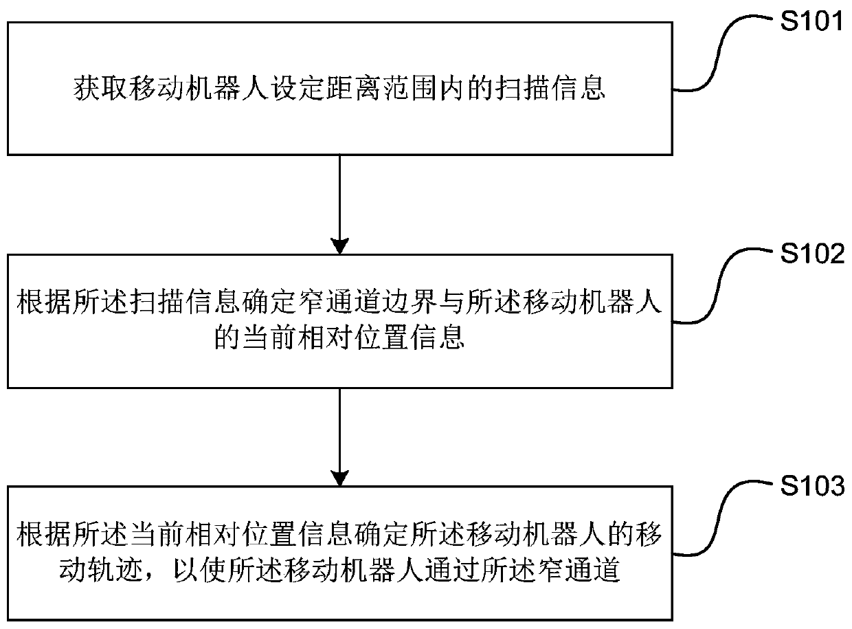
[0033] Embodiment 1 of the present invention provides a method for determining a movement trajectory. The method can be executed by a device for determining a movement trajectory, wherein the device can be implemented by software and / or hardware, and generally can be integrated in a mobile robot. figure 1 It is a schematic flow chart of the method for determining the movement trajectory provided by Embodiment 1 of the present invention, such as figure 1 As shown, the method includes:
[0034] S101. Obtain scanning information within a set distance range of the mobile robot.
[0035] Wherein, the scanning information may be the relative position information of the mobile robot and the obstacle, which may include information such as the direction and distance between the obstacle and the mobile robot. The set distance range can be set as required, and it can be greater than, equal to or smaller than the maximum scanning range of the mobile robot. Considering the accuracy of ...
Embodiment 2
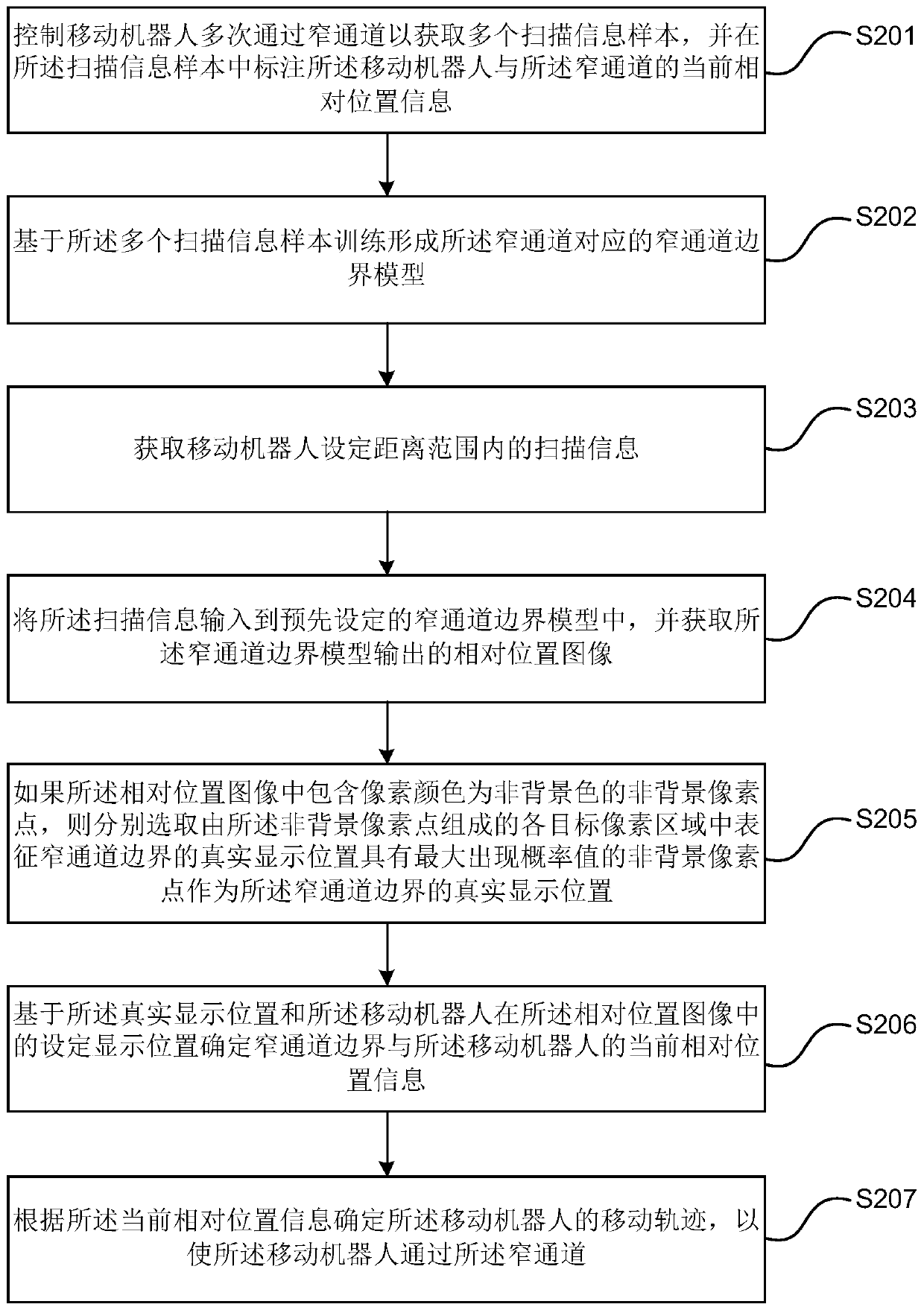
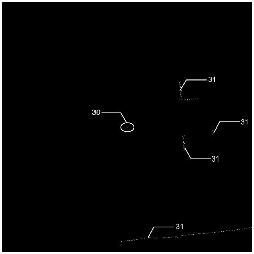
[0048] figure 2 It is a schematic flowchart of a method for determining a movement trajectory provided by Embodiment 2 of the present invention. This embodiment is optimized on the basis of the above-mentioned embodiments. In this embodiment, "determine the current relative position information between the narrow aisle boundary and the mobile robot according to the scanning information and the preset narrow aisle boundary model" Further optimization is: input the scan information into the preset narrow channel boundary model, and obtain the relative position image output by the narrow channel boundary model; if the relative position image contains For non-background pixel points, select the non-background pixel points with the maximum occurrence probability value as the real display position of the narrow channel boundary in each target pixel area composed of the non-background pixel points to represent the real display position of the narrow channel boundary , the image fea...
Embodiment 3
[0071] Figure 4 It is a schematic flowchart of a method for determining a movement trajectory provided by Embodiment 3 of the present invention. This embodiment is optimized on the basis of the above embodiments. Further, before determining the moving trajectory of the mobile robot according to the current relative position information, it further includes: determining that the narrow channel is the mobile robot Target narrow passage through which to reach the end position.
[0072] Further, before determining the moving track of the mobile robot according to the current relative position information, it also includes: determining the current scanning time according to the displacement information of the mobile robot and the last relative position information of the mobile robot Check the position information of the mobile robot and the boundary of the narrow channel; if the check position information is not the same as the current relative position information, Bayesian is ...
PUM
 Abstract
Description
Claims
Application Information
 - R&D
- Intellectual Property
- Life Sciences
- Materials
- Tech Scout
- Unparalleled Data Quality
- Higher Quality Content
- 60% Fewer Hallucinations
Browse by: Latest US Patents, China's latest patents, Technical Efficacy Thesaurus, Application Domain, Technology Topic, Popular Technical Reports.
© 2025 PatSnap. All rights reserved.Legal|Privacy policy|Modern Slavery Act Transparency Statement|Sitemap|About US| Contact US: help@patsnap.com


