
System and method for wireless power transfer using time reversed electromagnetic wave propagation

a technology of electromagnetic wave propagation and wireless power transfer, applied in the field of wireless power transfer, can solve the problems of low efficiency and practicality, low efficiency, and high impracticality, and achieve the effect of facilitating determination

Active Publication Date: 2019-05-09
UNIV OF MARYLAND
View PDF0 Cites 15 Cited by
  • Summary
  • Abstract
  • Description
  • Claims
  • Application Information

AI Technical Summary

Benefits of technology

This patent is about a system and method for wireless power transfer. It uses a technique called pulse-inversion to filter out specific frequencies and target either the initial emitter of the interrogation pulse or the non-linear object. This helps to isolate the non-linear signal and determine the location of the non-linear object. The technical effect of this patent is improved efficiency in wireless power transfer.

Problems solved by technology

Many techniques have been proposed for wireless power transfer (WPT) ranging from magnetic resonance to microwave beaming While the ability to transmit power practically and efficiently at short to mid-range is well-demonstrated in the literature, there is relatively little prior work that retains both high efficiency and practicality at distances beyond a few meters (S. Hui, et al., “A Critical Review of Recent Progress in Mid-Range Wireless Power Transfer,”Power Electronics, IEEE Transactions On,” vol.
Even in those cases where line of sight may be achievable, it is highly impractical due to the danger it introduces to humans or wildlife that may cross its path.
While safer than microwave beaming, these beacons still have a relatively limited range (S. Hui, et al., “A Critical Review of Recent Progress in Mid-Range Wireless Power Transfer,”Power Electronics, IEEE Transactions On,” vol.
This method suffers from bandwidth limitations in general (C. Prada, et al., “The Iterative Time Reversal Mirror: A Solution to Self-Focusing in the Pulse Echo Mode,”The Journal of the Acoustical Society of America, vol.

Method used


Image

  • System and method for wireless power transfer using time reversed electromagnetic wave propagation
  • System and method for wireless power transfer using time reversed electromagnetic wave propagation
  • System and method for wireless power transfer using time reversed electromagnetic wave propagation

Examples


Embodiment Construction

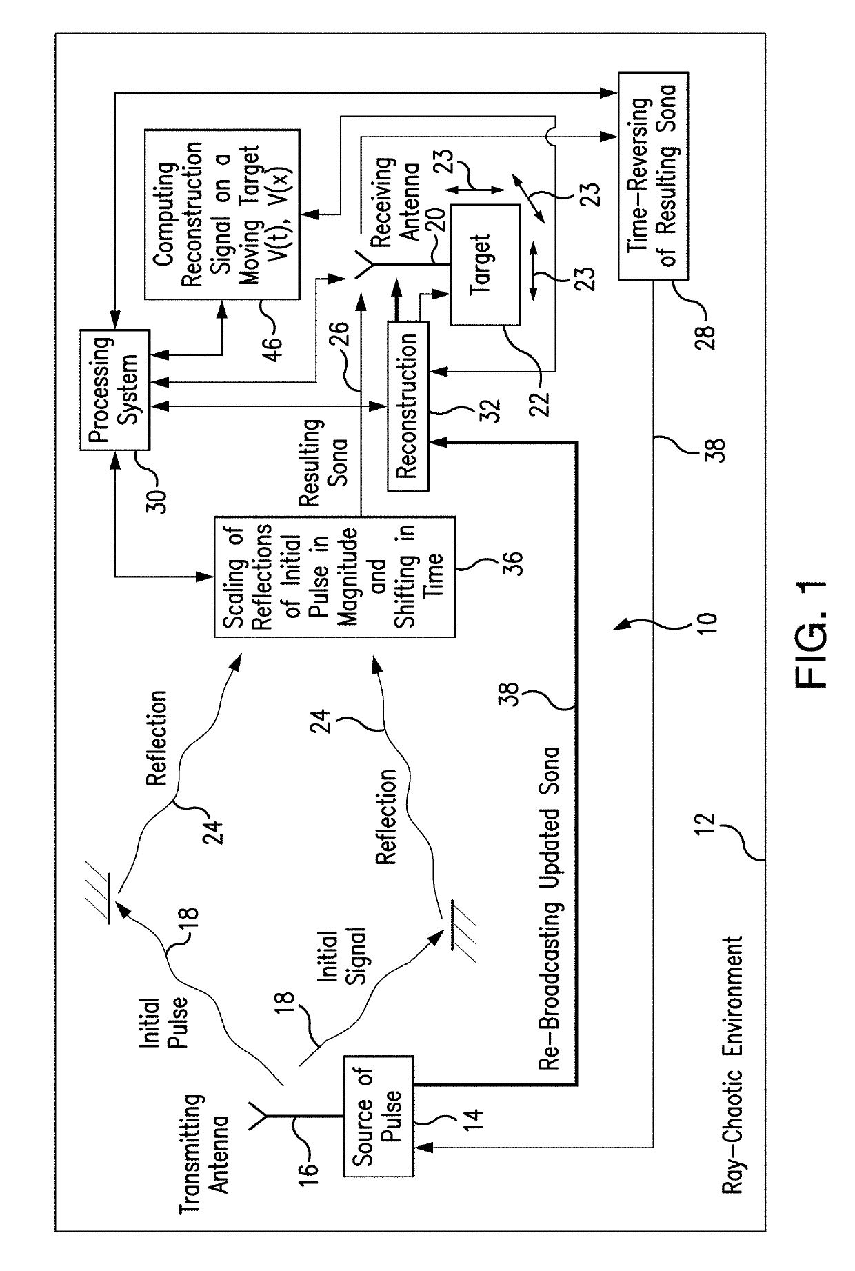
[0094]The present system uses electromagnetic waves time-reversed technique for wireless power transmission. The subject system presented in FIGS. 1, 6A, 11A, and 13A, operates in several modes of operation, including:

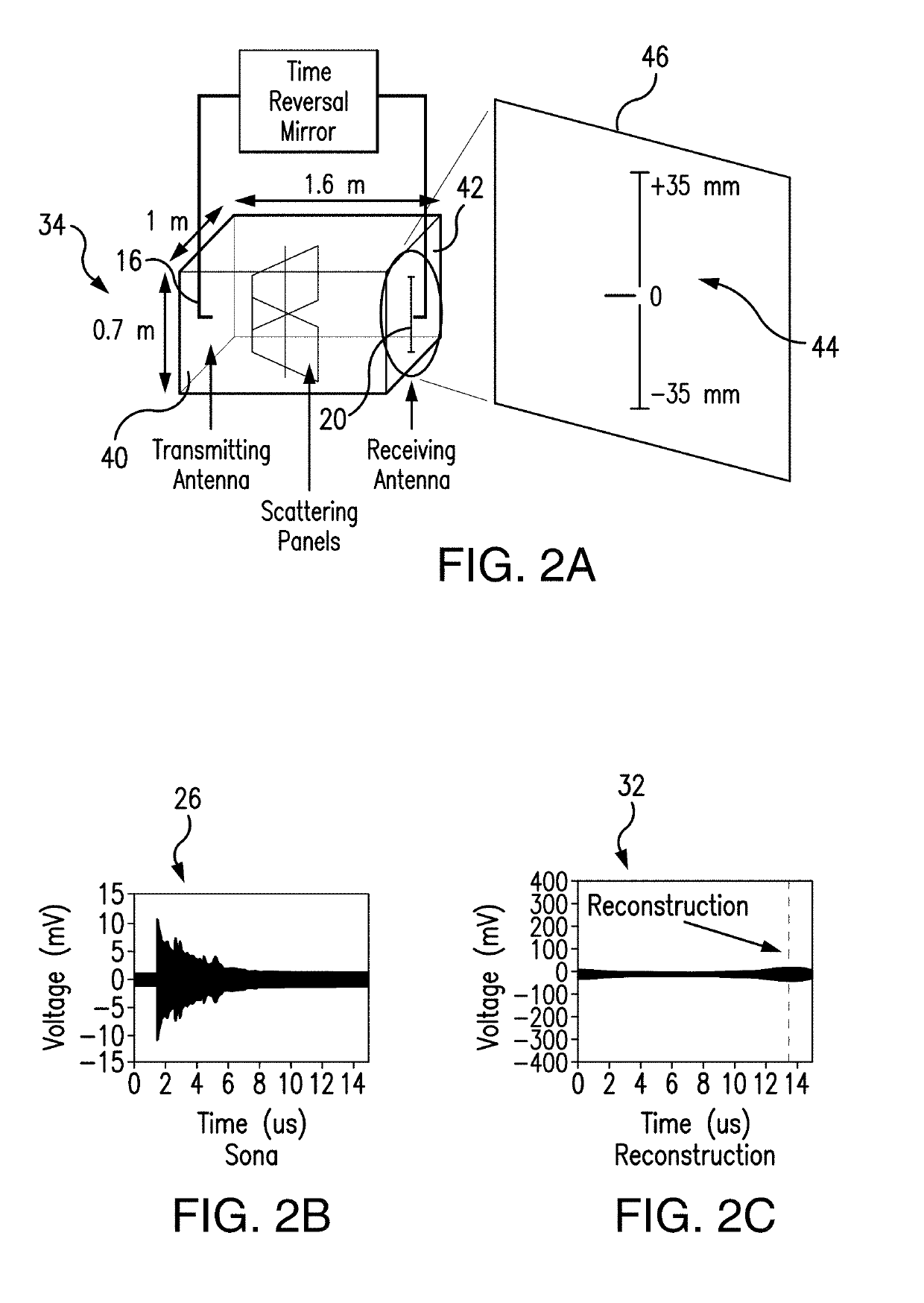
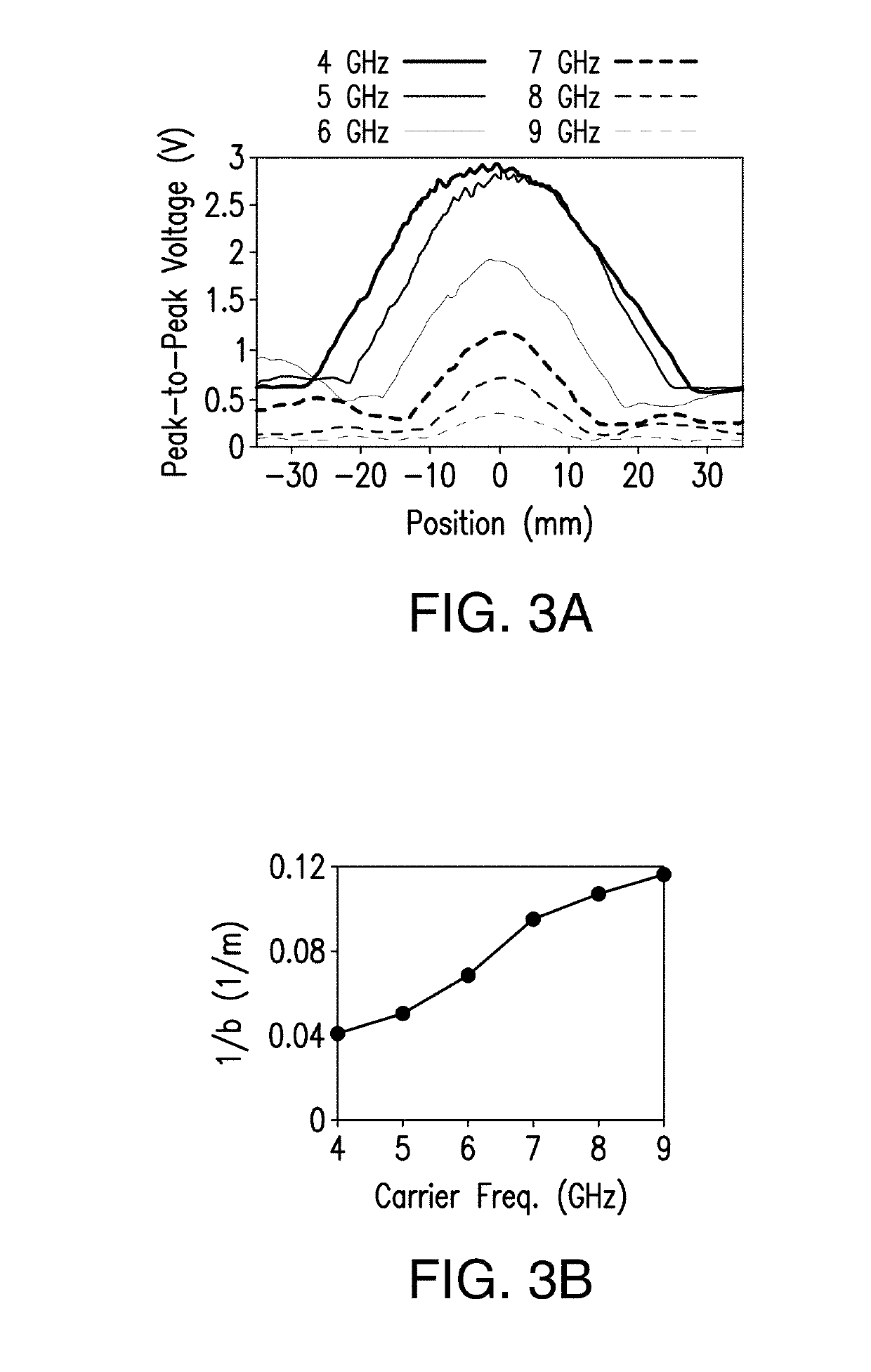
[0095](a) mode of operation for delivering power to a moving target wirelessly via electromagnetic (EM) waves focusing time reversal technique, as shown in FIGS. 1-5; and

[0096](b) mode of operation for selective power delivery to a target of interest using non-linear time-reversed EM waves, as depicted in FIGS. 6A-13.

[0097]The present invention is a method and system designed to transmit power to a moving target of interest using the wave focusing time reversal technique.

[0098]Performing linear TR in an enclosure requires four steps:

[0099](1) Broadcast an initial interrogation pulse into the enclosure at location A;

[0100](2) As the pulse reverberates in the cavity, record a response signal, also called a sona, at another location B;

[0101](3) Flip the recorded sona wave...


PUM


Abstract

The subject method for delivering power to a moving target wirelessly via electromagnetic time reversal can find applications in wireless electrical transmission to portable devices, wireless heating of portable devices, novel wirelessly powered accelerometers, hyperthermic treatment of cancers, and many other applications. The subject non-linear time reversed electromagnetic waves based wireless power transmission (WPT) system targets either a single linear or non-linear object where a selective targeting between two diodes has been demonstrated simultaneously with different degrees of non-linearity in a three-dimensional ray-chaotic billiard model. A dual-purpose rectenna with harmonic generation for wireless power transfer by non-linear time-reversal has been designed for the subject system using the Schottky diode.

Description

REFERENCE TO THE RELATED APPLICATIONS[0001]This Utility Patent Application is based on Provisional Patent Applications Nos. 62 / 327,346 and 62 / 327,349, both filed on 25 Apr. 2016.STATEMENT REGARDING FEDERAL SPONSORED RESEARCH OR DEVELOPMENT[0002]This invention was made with Government support under Contract N000141512134 awarded by ONR. The Government has certain rights in the invention.FIELD OF THE INVENTION[0003]The present invention is directed to the field of wireless power transfer in ray-chaotic environments, and more in particular, to wireless power transfer using time reversal technique.[0004]The present invention is further directed to time reversed electromagnetic wave propagation to transmit energy to a moving target in a reverberant complex scattering environment.[0005]The present invention is also directed to a system and method for wireless transmission of power to multiple receiving devices at the same time with selection of users to receive power to the exclusion of o...

Claims


Application Information

Patent Timeline
IPC IPC(8): H04K1/06H02J50/20H02J50/90H04K3/00
CPCH04K1/06H02J50/20H02J50/90H04K3/62H04K3/68H04K1/00H02J50/23H02J50/27H02J50/15H04B11/00
Inventor ANLAGE, STEVEN MARKCANGIALOSI, FRANKGROVER, TYLERSIMON, ANDREWROMAN, SCOTTTAO, LIANGCHENG
Owner UNIV OF MARYLAND
Learn More