
Flow cell and system for simultaneous measurement of absorbance and emission in a sample

Active Publication Date: 2019-05-02
BIOCOMP INSTR
View PDF8 Cites 0 Cited by
  • Summary
  • Abstract
  • Description
  • Claims
  • Application Information

AI Technical Summary

Benefits of technology

The flow cell described in this patent has several technical benefits. It can manage low flow rates and has a design that minimizes mixing and turbulence. It allows simultaneous measurement of absorbance and fluorescence, and can measure multiple wavelengths in the UV-IR spectrum. The flow cell also has a modular design that allows users to tailor its capabilities to their needs. Additionally, it uses an electronic means to display, record, save, and manipulate multiple digital data streams. Overall, the flow cell described in this patent provides high-quality, low-distortion flow analysis for a wide range of applications.

Problems solved by technology

However, neither of these flow cell designs are of use where separation of particles of interest is the goal, as it is in chromatography (e.g. FPLC and HPLC) and density gradient centrifugation.
In the flow cell of U.S. Pat. No. 8,649,005, the protruding light guides may give variable path length, but they also disrupt the smooth flow of the liquid moving around them and through the gap between them.
If the input liquid represents a stream of particles separated from each other by some means, the resultant turbulence, the comparatively large volume of the flow cell and the large surface area of its threaded light probes will produce smearing of the flowing liquid and a resultant loss of resolution.
Additionally, this design is incompatible with fluorescence detection where a large volume of sample needs to be queried to produce a reasonable fluorescence signal.
In addition, the example fluorescence flow cells discussed above are unable to measure absorbance.
As well, the flow cell of U.S. Pat. No. 3,728,032 cannot measure fluorescence.
Particularly, this design views the liquid flow from outside a round glass tubing that contains the flow, which may result in a large loss of light that is compensated for with a fluorescent reflector.
As well, the volume of liquid from which fluorescence and absorption signals are measured is very large, resulting in a low resolution in the flow cell which is not suitable for density gradient applications.
However, it is designed for industrial online flow analysis applications, not for low volume separation technologies.
Its adjustable path length (0.5-15 mm) indicates that it has the same disruptive interior design as the flow cell of U.S. Pat. No. 8,649,005, making it unsuitable for use with, for example, separation technologies.

Method used


Image

  • Flow cell and system for simultaneous measurement of absorbance and emission in a sample
  • Flow cell and system for simultaneous measurement of absorbance and emission in a sample
  • Flow cell and system for simultaneous measurement of absorbance and emission in a sample

Examples


second embodiment

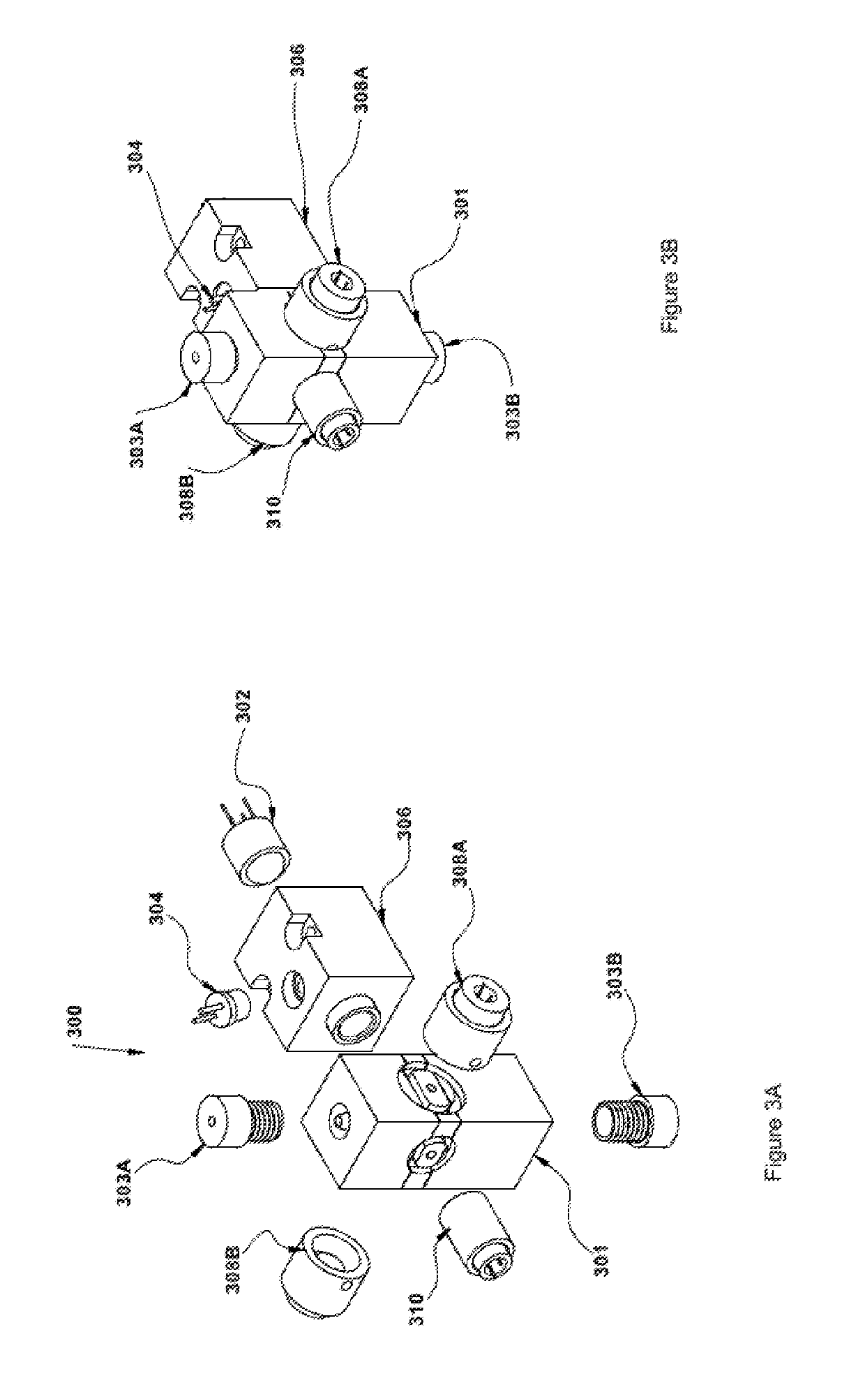
[0072]FIG. 5A is an exploded view and FIG. 5B is a perspective view of a flow cell apparatus 500 incorporating the flow cell 100 of FIG. 1 and having two light inputs and two light outputs, as well as two photodiodes for fluorescence measurement, thereby facilitating two simultaneous light absorption measurements and fluorescence emission, according to the present application. The flow cell apparatus 500 may permit two UV absorbance measurements, one UV absorbance measurement and one visible light measurement or two visible light wavelengths, as well as one or two emission wavelengths.

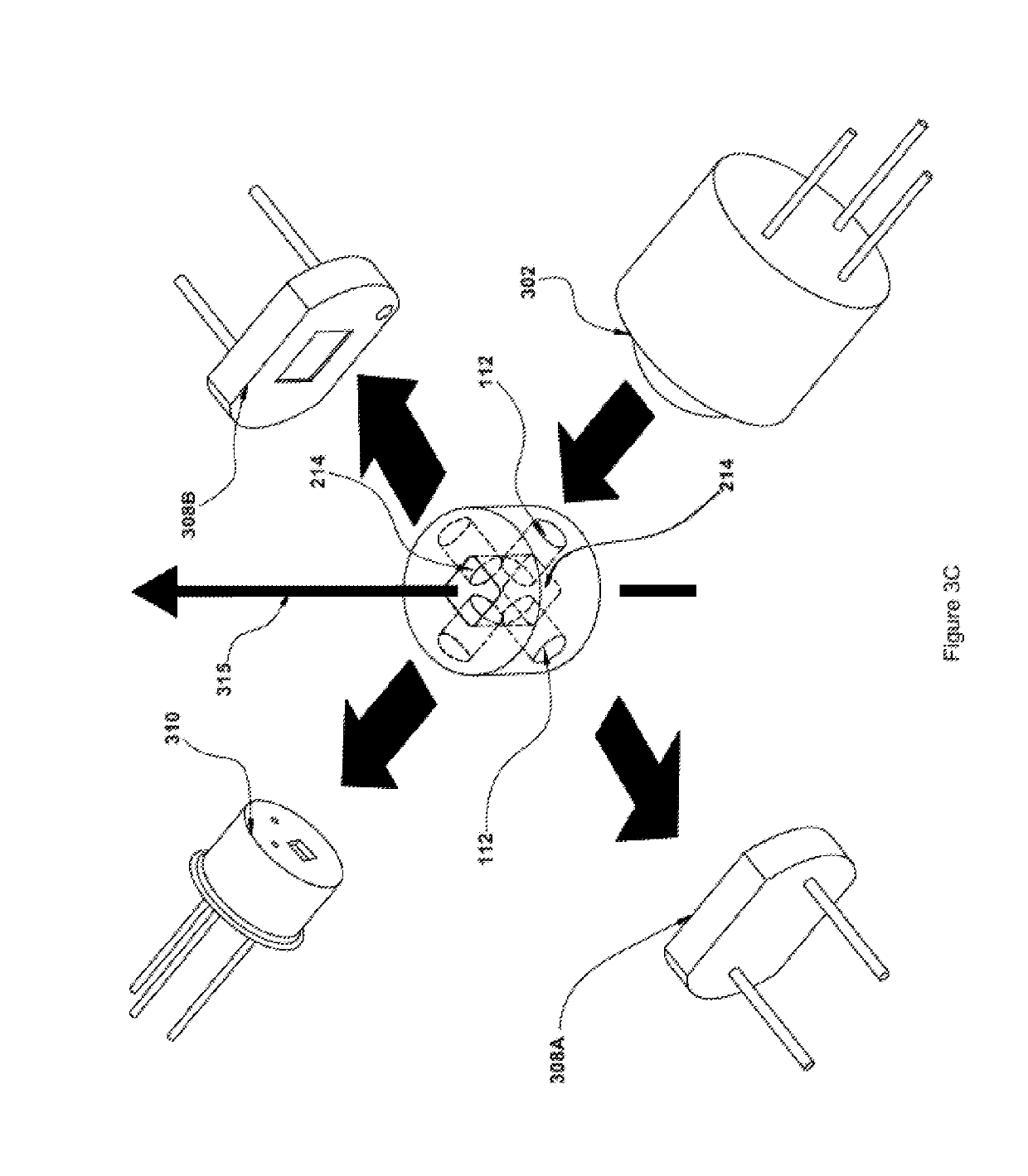
[0073]With the flow cell apparatus 500, one or more different wavelengths of excitation light may be transmitted into the central chamber 214 through the light input face using appropriate light sources, fiber optic bundles and / or light filters.

[0074]As well, with the flow cell apparatus 500, one or more different wavelengths of absorbed light may be measured independently and simultaneously at the abs...

third embodiment

[0081]FIG. 8A is an exploded view and FIG. 8B is an enlarged perspective view of a three input module 800 for use with a flow cell 100, according to the present application. The three input module 800 of the may receive as inputs three UV wavelengths (e.g. 3 UV), three visible light wavelengths (e.g. 3 VIS), two UV wavelengths and one visible light wavelength or vice versa (e.g. 2 UV and 1 VIS or 1 UV and 2 VIS). As shown in FIG. 8, there are three input light sources 802A, 802B, 802C (e.g. LEDs), each of which focus their light beams on trifurcated fiber optic bundles (e.g. separate input arms) 808A, 808B, 808C that join with the combined fiber optic light pipe 810. The separate input arms of the fiber optic bundles 808A, 808B, 808C meet and the light they carry is mixed in the single bundle 810, so that they provide even illumination to the fiber optic light pipe 112 (e.g. quartz light rod) that carries the light beam into the flow cell's 214 central core. The input light sources ...


PUM


Abstract

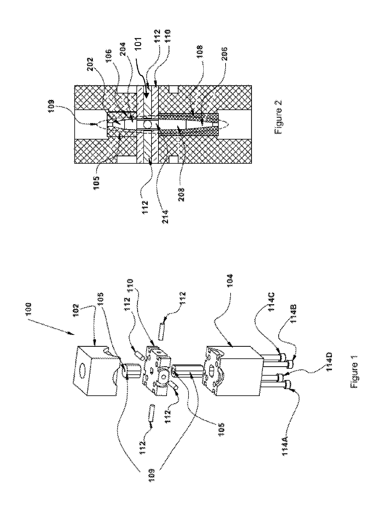
The flow cell of the present application simultaneously monitors and measures light absorbance and fluorescence of particles in a flowing liquid. The flow cell comprises a housing having a light input face, an absorbance output face and first and second emission output faces; a fluid flow section within the housing that comprises a bottom funnel through which fluid enters the flow cell, a core chamber into which fluid flows from the bottom funnel, and a top funnel into which fluid flows from the core chamber, wherein the bottom and top funnels each comprise a first end which extends at an angle to a second end that is wider in diameter than the first end, and said second end of each is adjacent to and aligned with the core chamber; and a center section within the housing center having a recess formed therein which houses the core chamber of the fluid flow section, wherein said center section comprises a first pair of opposing channels formed in the light input face and the absorbance output face, respectively, and a second pair of opposing channels formed in the first emission output face and the second emission output face and which are perpendicular to the first pair of opposing channels, and wherein the first pair of opposing channels and second pair of opposing channels are in communication with the core chamber. An apparatus comprising the flow cell is also provided.

Description

FIELD OF THE INVENTION[0001]The present application relates to an apparatus for monitoring particles in a flowing liquid. In particular, the present application relates to a flow cell and apparatus for monitoring and measuring the absorbance and fluorescence of particles in a flowing liquid.BACKGROUND OF THE INVENTION[0002]Chromatographic and density gradient separation of particles are utilized in biochemical research to separate macromolecules such as proteins, DNA and RNA, and larger aggregates such as enzyme complexes, ribosomes, viruses and cells. With such applications, it may be necessary to monitor the absorbance and fluorescence of particles within a flowing liquid sample, typically within a flow cell. Ultraviolet-visible spectroscopy (UV-Vis or UV / Vis) refers to absorption spectroscopy or reflectance spectroscopy in the ultraviolet-visible spectral region, where absorption measures transitions from the ground state to the excited state. Fluorescence spectroscopy deals with...

Claims


Application Information

Patent Timeline
IPC IPC(8): G01N21/05G01N21/17B01D15/40G01N21/64
CPCG01N21/05G01N21/17B01D15/40G01N21/645G01N2021/174G01N2021/0346G01N21/31G01N2021/6482G01N2021/6484B01L3/502715B01L2200/027B01L2300/0654B01L2300/0663G01N15/1459
Inventor COOMBS, DAVIDCOOMBS, AUGUST
Owner BIOCOMP INSTR
Learn More