
Micro-lens imaging multi-well test plate

a multi-well, micro-lens technology, applied in the field of optical detecting technology, can solve the problems of inability to perform non-disturbance in situ rapid detection, abbe refractometer, and inherent limitations of current methods

Active Publication Date: 2019-04-25
JINAN UNIVERSITY
View PDF12 Cites 5 Cited by
  • Summary
  • Abstract
  • Description
  • Claims
  • Application Information

AI Technical Summary

Benefits of technology

The invention is a micro-lens imaging multi-well test plate that can non-invasively detect changes in the refractive index of a solution. It can measure changes with high accuracy and without the need for labeling or post-modification, and can detect low amounts of substances present in the solution. The test plate has trapezoidal wells that ensure optimal optical imaging quality. The detection is objective and can occur on very small sample volumes, and the detection limit is extremely low. The invention also allows for multi-path detection of different samples simultaneously.

Problems solved by technology

Known methods exist for refractive index detection, but the current methods have inherent limitations.
Such as Abbe refractometer, cannot perform non-disturbance in situs rapid detection on the instantaneous variation of the local or bulk refractive index of a solution.
None of the conventional methods is able to determine the individual refractive indices of several different samples in one measurement.
The monitor of the refractive index variation in a solution requires methods which can perform non-disturbance in situs rapid detection on the instantaneous value of local or bulk refractive index of the solution, but none of the conventional methods can satisfy the requirements.
Furthermore, none of the conventional methods is able to determine the individual refractive indices of several different samples in one measurement.

Method used


Image

  • Micro-lens imaging multi-well test plate
  • Micro-lens imaging multi-well test plate
  • Micro-lens imaging multi-well test plate

Examples


Embodiment Construction

[0025]The following examples and drawings depict an implementation of the presently claimed invention in further detail.

In a First Illustrative Example

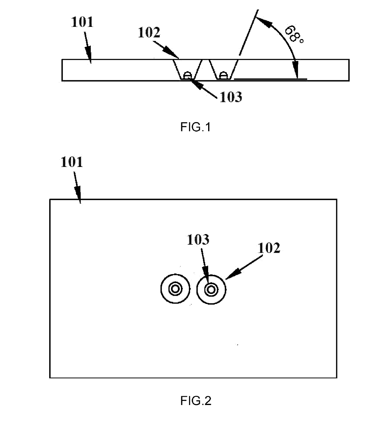
[0026]The micro-lens imaging 2-path multi-well test plate comprises: a transparent PMMA plate with thickness of 3.5 mm, two trapezoidal wells which underside is 2.5 mm in diameter, 0.25 mm in thickness, and trapezoidal dip angle is 68°; and has a micro-lens with radius of 0.35 mm, height of 1.0 mm molded on the bottom of each well.

[0027]The whole micro-lens imaging multi-well test plate is injection molded in one step, its transparency is >90%, mirror finish is Ra 0.025, and under hydrophilic treatment with a hydrophilic treatment reagent DP-9993 (a terpolymer of polyester-polyether-organosilicon) for 24 hours at room temperature.

[0028]By dropping some sample fluid into said test well to submerse said micro-lens, and placing said micro-lens imaging multi-well test plate under a phase contrast microscope for imaging, an image of said m...


PUM


Abstract

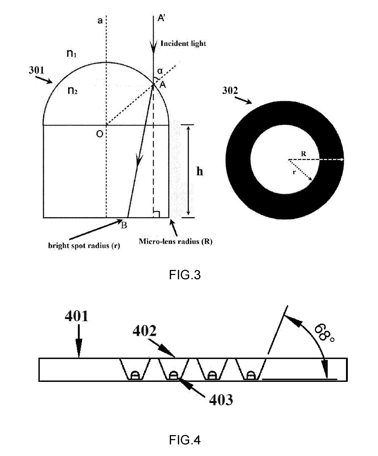
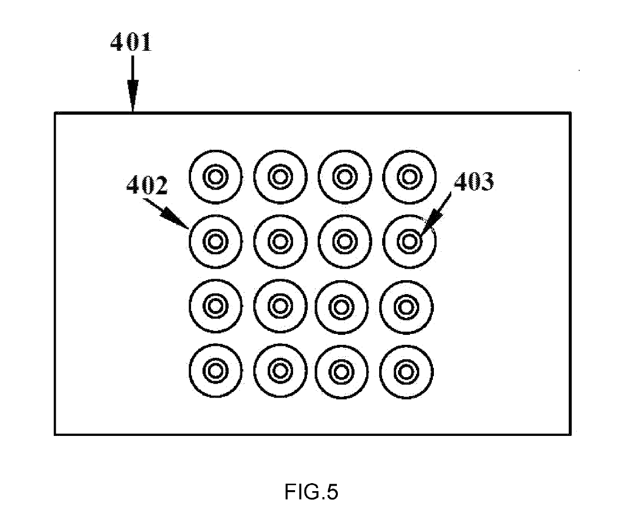
Disclosed is a micro-lens imaging multi-well test plate which comprises: a transparent plate of 3-5 mm in thickness with one or more trapezoidal wells locating in the middle of the plate, each of the wells is of an underside of 2-4 mm in diameter, 0.2-0.5 mm in thickness, a trapezoidal dip angle of 60-75°, and has a micro-lens which upper half is hemispherical, lower half is a cylinder, with radius of 0.1˜1.0 mm, height of 0.2˜2.5 mm, molded on the bottom of the well. The micro-lens imaging multi-well test plate is made of homogeneous optical transparent materials. When the trapezoidal concave wells of the test plate are filled with fluid to immerse the micro-lens, under parallel light illumination, due to the refraction effect of light, the image of micro-lens is a round one with an outer edge that is a black ring. The outer radius R of the black ring is the radius of the micro-lens, the inner radius r of the black ring is a function of the refractive index n1 of the immersion liquid, the refractive index n2 of the micro-lens and the height h of the micro-lens, so the refractive index of the sample fluid can be determined by monitoring the value of the inner radius r of the black ring with known values of R, n2 and h. By using a multi-well test plate for imaging, the individual refractive indices of different sample fluids in all the wells can be determined simultaneously in one measurement.

Description

CROSS REFERENCE TO RELATED APPLICATIONS[0001]This application claims priority to China Application Number PCT / CN2017 / 076565 filed on Mar. 14, 2017.BACKGROUND OF INVENTIONTechnical Field[0002]The claimed invention is related to optical detecting technology, particularly involving a micro-lens imaging multi-well test plate for the detection of fluid refractive index.Description of Related Art[0003]Known methods exist for refractive index detection, but the current methods have inherent limitations. Such as Abbe refractometer, cannot perform non-disturbance in situs rapid detection on the instantaneous variation of the local or bulk refractive index of a solution. None of the conventional methods is able to determine the individual refractive indices of several different samples in one measurement.[0004]Refractive index is one of the most important physical properties of a solution or a medium which is a function of the solution concentration and temperature. Therefore, by detecting th...

Claims


Application Information

Patent Timeline
IPC IPC(8): G01N21/41G01N21/43G02B13/00
CPCG01N21/4133G01N21/431G02B13/0055G01N2201/0639G01N21/41G01N2201/0638G01N21/0303G01N21/253G01N2021/0307G01N2021/0382G02B3/0056
Inventor HUANG, YAOXIONGHE, JIANG
Owner JINAN UNIVERSITY
Learn More