Combination sensor

a sensor and combination technology, applied in the field of combination sensors, can solve the problem of no further optical measurement system, and achieve the effect of reliable identification of objects

Active Publication Date: 2019-04-18
SCHLEUNIGER
View PDF0 Cites 0 Cited by
  • Summary
  • Abstract
  • Description
  • Claims
  • Application Information

AI Technical Summary

Benefits of technology

[0006]It is the object of the present invention to provide an improved sensor arrangement which uses synergies of various measuring systems so that a compact, functionally robust design of a combination sensor is obtained which enables the determination of several characteristics of the object in order to enable a reliable identification of the object to be made from this.

Problems solved by technology

Furthermore, no further optical measuring system is provided.

Method used


Image

  • Combination sensor
  • Combination sensor
  • Combination sensor

Examples


Embodiment Construction

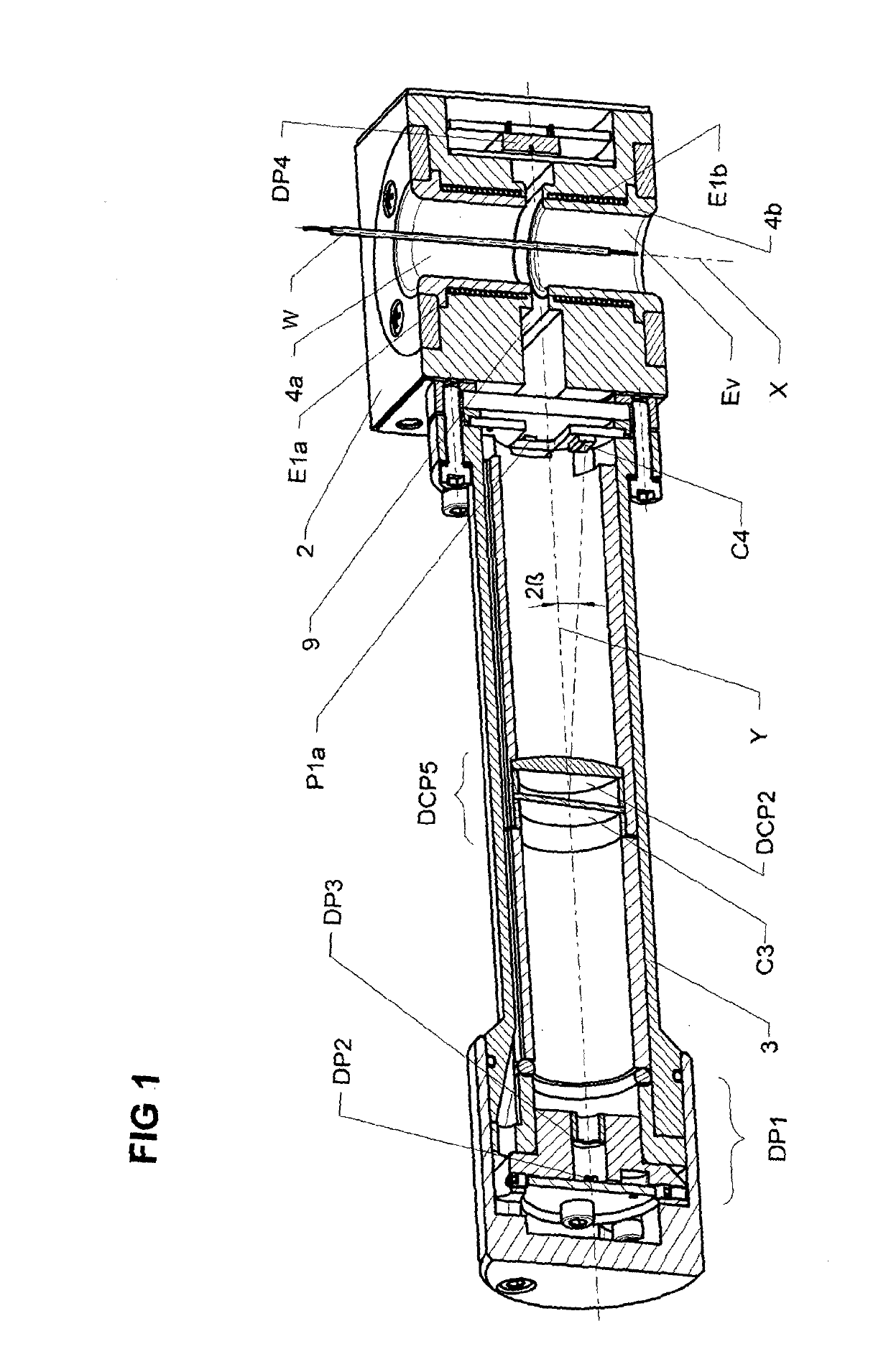
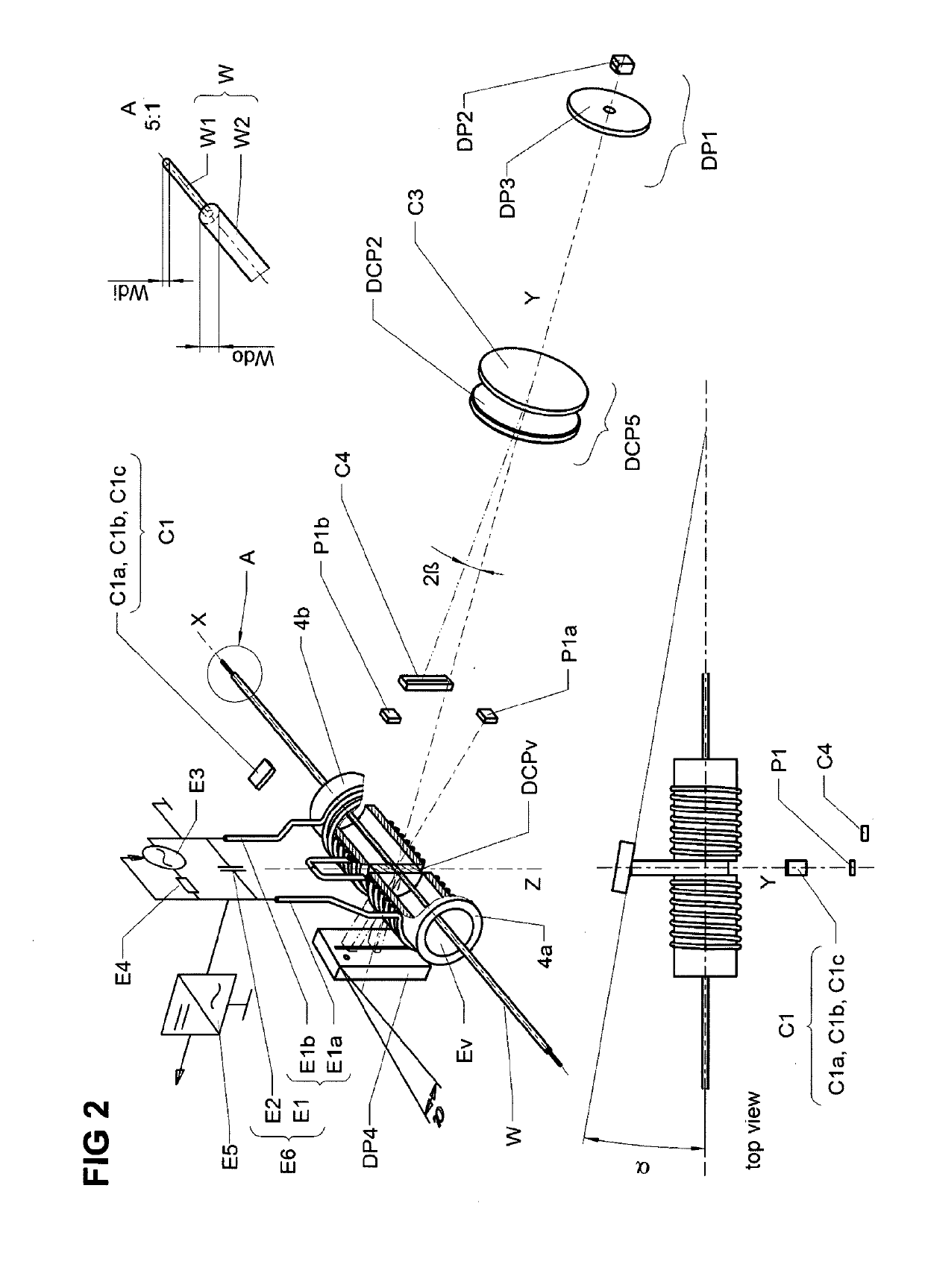
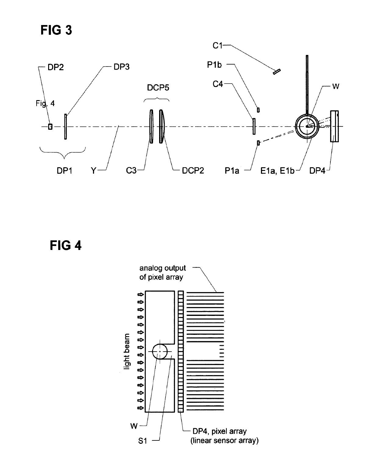
[0036]FIG. 1 shows an exemplary embodiment of a sensor arrangement such as is preferably positioned in front of or at the input of a processing machine for elongate objects, in particular for processing machines for cable or the like in order to enable a reliable identification of the cable to be processed as measurement object W. On the input side a housing 2 as well as a tube 3 with a part of the optical system of the sensor arrangement are fastened on the processing machine. The elongate object W is guided in the axial direction and before the beginning of the actual processing through the cable jacks 4a, 4b as a guide device in the housing 2.

[0037]During the through-movement of the object W or also during a standstill time, the outside diameter and the colour of the object W are determined. In addition, the position of the object inside the cable jacks 4a, 4b can be determined. The sensors for determining these measured quantities and therefore the measuring systems for the outs...


PUM

PropertyMeasurementUnit
optical measuringaaaaaaaaaa
diameteraaaaaaaaaa
volumeaaaaaaaaaa

Abstract

An arrangement for automatically contactlessly detecting elongate objects (W), such as cables, wires or profiles, has a quasi-coaxially arranged group of a first optical measuring system (D) for determining the external diameter and a second optical measuring system (C) for determining the color using a different measurement principle. The functional and local separation of the two measuring systems (C, D) is achieved by using different wavelength ranges and by a long-pass filter (C3). A third, virtual measuring system (P) may be provided for the purpose of determining the cable location and is used to weight measured values of the color measurement and measured values of an optional eddy current sensor. The optical measuring systems (D, C, P) for determining the diameter, the color and the position have a common optical disc-shaped measuring volume (DCPv) which is preferably arranged centrally in the guide device (4a, 4b) for the elongate object (W).

Description

[0001]This application is a National Stage completion of PCT / IB2017 / 000355 filed Mar. 31, 2017, which claims priority from European patent application serial no. 16163593.8 filed Apr. 1, 2016.FIELD OF THE INVENTION[0002]The invention relates to an arrangement for automatically detecting elongate objects such as cables, wires or profiles using at least two optical measuring systems based on different measurement methods and an installation using such an arrangement.BACKGROUND OF THE INVENTION[0003]In processing machines for cable, wires or similar elongate objects, it must be ensured by reliable identification of the objects that the type of processing, the settings of the machine and their parameters are tuned to the respective object and the requirements defined by the user. To this end measuring systems are preferably arranged in front of or at the input of the processing machine, which should enable a reliable identification of the elongate object. These comprise a plurality of s...

Claims


Application Information

Patent Timeline
Patent Type & Authority Applications(United States)
IPC IPC(8): G01B11/10G01B7/02G01J3/50G01N21/952
CPCG01B11/10G01B7/023G01J3/501G01N21/952G01B7/12G01B7/125G01B11/08
Inventor DESCHLER, RAPHAELJOST, MICHAELHUGGLER, CHRISTIANHOFER, RETO
Owner SCHLEUNIGER
Why Eureka
Try Eureka