
Time synchronisation method, insensitive to power variations, associated receiver and computer program

a time synchronisation and power variation technology, applied in the field of data communication systems, can solve the problem that the gain adjustment of the gain control unit is not necessarily precise, and achieve the effect of reducing the imprecision of the gain adjustment and improving the detection performance of the ideal synchronisation instan

Active Publication Date: 2019-04-11
COMMISSARIAT A LENERGIE ATOMIQUE ET AUX ENERGIES ALTERNATIVES
View PDF1 Cites 2 Cited by
  • Summary
  • Abstract
  • Description
  • Claims
  • Application Information

AI Technical Summary

Benefits of technology

This invention proposes a method for synchronizing equipment that is less sensitive to changes in gain adjustments and improves the detection of the ideal synchronization point.

Problems solved by technology

Yet, the gain adjusted by the gain control unit is not necessarily precise and depends on several factors, such as the precision of the “digital” power estimation at the output of the converters.

Method used


Image

  • Time synchronisation method, insensitive to power variations, associated receiver and computer program
  • Time synchronisation method, insensitive to power variations, associated receiver and computer program
  • Time synchronisation method, insensitive to power variations, associated receiver and computer program

Examples


Embodiment Construction

[0025]The invention is based on a method of synchronising an input signal in a receiver of a communication system. This method is implemented in a time synchronisation unit that equip the receiver, the latter also comprising a gain control unit.

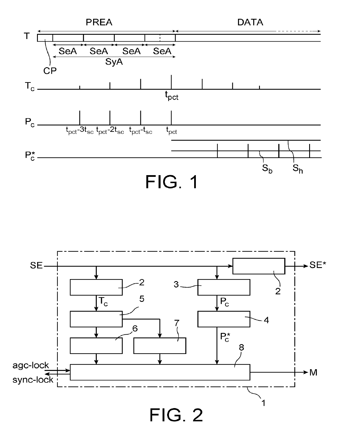
[0026]The input signal carries data frames. As represented in FIG. 1, each frame T comprises a preamble PREA followed by a portion DATA carrying a succession of data symbols. The preamble PREA comprises at least one learning symbol SyA dedicated to the synchronisation search which is formed of N repetitions of a learning sequence SeA (N being an integer greater than or equal to 2; N=4 in the example in FIG. 1). The learning sequence SeA comprises Ns samples, for example 16 samples. The learning symbol SA, as well as the data symbols, can be preceded by a cyclic prefix CP.

[0027]The synchronisation according to the invention is implemented once the gain adjustment phase has been completed. The method thus comprises a prior step of adjusting the...


PUM


Abstract

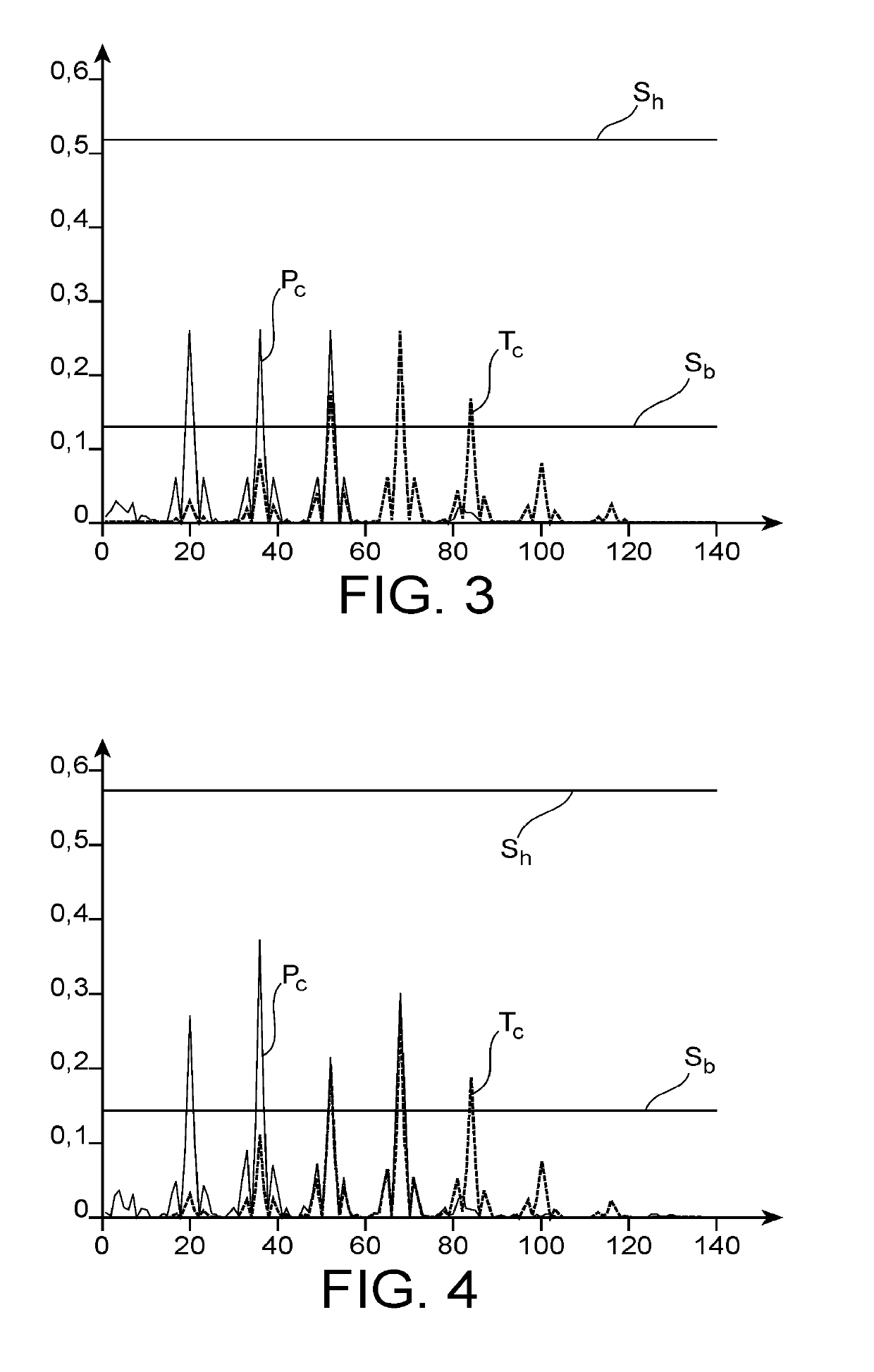
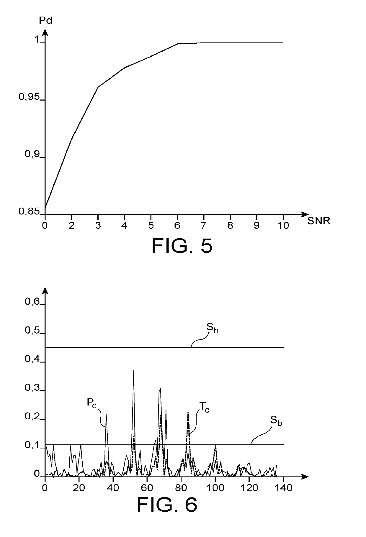
A method of synchronising a communication signal entering into a receiver. Each frame of the signal includes a learning symbol formed of N repetitions of a learning sequence. The method includes the determination of a total correlation signal by correlating the input signal with a correlation symbol formed of N repetitions of a correlation sequence corresponding to all or part of the learning sequence and duration tsc, and the determination of a partial correlation signal by correlating the input signal with the correlation sequence. A peak of the total correlation signal is identified at an instant tpct. At least one threshold is defined from the power of the peak of the total correlation signal, and the power of the partial correlation signal is compared here to the instants tpct−k*tsc, with k a whole number between 0 and N−1.

Description

TECHNICAL FIELD[0001]The field of the invention is that of data communication systems, and more specifically, that of time synchronisation of data packets made by a receiver of a communication system. The invention advantageously finds application in decoding signals carrying data frames where each frame comprises a learning symbol formed from the repetition of a learning sequence, like for example OFDM (“Orthogonal Frequency Division Multiplex”) signals, in particular, OFDM signals with a CP (“Cyclic Prefix”) or FDE (“Frequency Domain Equalisation”).PRIOR ART[0002]Within a receiving chain of a receiver of a wireless communication system, data from an antenna enter into a gain control unit which has the role of adjusting the gain of an RF amplifier such that an analogue-to-digital converter arranged downstream of the amplifier works in the linear zone thereof.[0003]Once this gain is adjusted, a time synchronisation of the entering dataflow must be made, which consists of determining...

Claims


Application Information

Patent Timeline
Patent Type & Authority Applications(United States)
IPC IPC(8): H04L7/00H04B1/16
CPCH04L7/0079H04B1/16H04L7/007H04B1/70752H04B1/7077H04B1/7087H04L27/2663H04L27/2675H04L27/2688
Inventor LAUGEOIS, MARC
Owner COMMISSARIAT A LENERGIE ATOMIQUE ET AUX ENERGIES ALTERNATIVES
Learn More