
Multi-pump system with system check

a multi-pump system and check technology, applied in the direction of pump control, positive displacement liquid engine, fluid engine, etc., can solve the problems of major water damage, unexpected pump failure is the akeley's heel of the conventional pump system, and serious water damage, so as to shorten the motor's life, save electricity, and improve the effect of efficiency

Active Publication Date: 2019-03-21
LIGHTING TAIWAN
View PDF0 Cites 0 Cited by
  • Summary
  • Abstract
  • Description
  • Claims
  • Application Information

AI Technical Summary

Benefits of technology

The described patent pump system uses multiple smaller pumps to better match the water seeping rate and reduce the risk of pump failure. It also converts high voltage AC power to low voltage DC power and stores it in a reservoir to supply power during a grid outage. This design not only provides pumping power support but also alleviates the threat of high voltage electrocution. Additionally, the system uses small pumps that are designed to better match the seeping rate, reducing motor actions during normal seeping and increasing the system's capacity.

Problems solved by technology

Statistically speaking, when using the conventional pump system, the most frequent cause of serious water damage is due to unexpected pump failures that lead to basement flooding.
Unexpected pump failure is the Akeley's heel of the conventional pump system which operates using a single pump.
The second most frequent cause of major water damage when using the conventional pump system is due to grid power outages.
But use of the conventional pump system also has other potential concerns, in addition to water damage.
For instance, there is a threat of high voltage electrocution when there is flooding.
This system reduces the severe consequences of pump failure, since redundant pumps now exist in case of failure of any given pump.
These events might include pump failure during normal operation, grid power outage and recovery, water influx rate exceeding the pump system's capacity, and so forth.
As a result, during the normal seeping rate, there is a periodic short pulsed start-then-stop pumping action that can shorten the motor's life and also waste a lot of electric energy.
Secondly, a single big pump is designed with no spare pumping capacity to handle a larger than designed maximum seeping rate.
Even if the seeping rate exceeds the pumping rate by just 10% for a short time; there may still be water damage.

Method used


Image

  • Multi-pump system with system check
  • Multi-pump system with system check
  • Multi-pump system with system check

Examples


Embodiment Construction

[0023]Section One: Conventional pump systems.

[0024]Statistically speaking, when using the conventional pump system, the most frequent cause of the serious water damages is due to unexpected pump failures that lead to basement flooding. Unexpected pump failure is the Akeley's heel of the conventional pump system which operates using a single pump. The second most frequent cause of major water damage when using the conventional pump system is due to grid power outages. But use of the conventional pump system also has other potential concerns, in addition to water damage. For instance, there is a threat of high voltage electrocution when there is flooding.

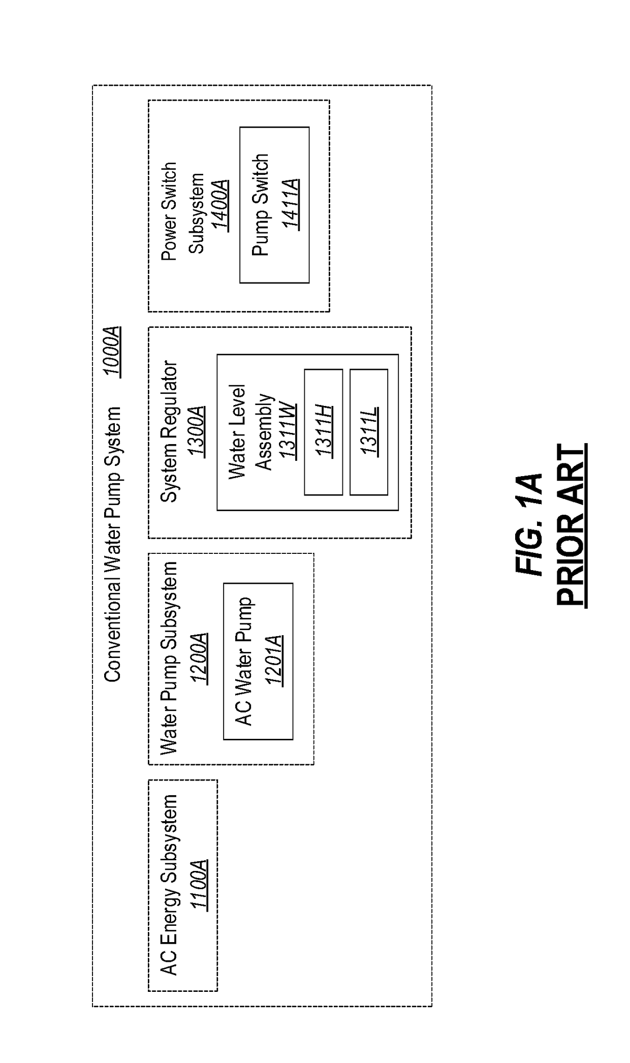
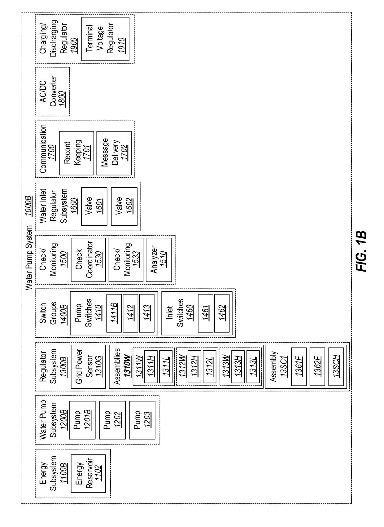
[0025]FIG. 1A schematically illustrates a conventional pump system 1000A. In contrast, FIG. 1B schematically illustrates an embodiment of a pump system 1000B in accordance with the principles described herein. As depicted in FIG. 1A, a conventional pump system 1000A includes (1) a power supply subsystem (or “energy subsystem”) 1100A t...


PUM


Abstract

Design solutions to mitigate the following four fatal flaws in the conventional pump system design; namely, (1) surprise pump-failure in single pump designs that can result in costly water damage; (2) the threat of fatal high voltage electrocution due to flooding; (3) grid power outage and no energy supply to support the needed pumping power that results in water damage; (4) foil odor from the standing water in the well after a period of low seeping rate with or without activated pumping. The principles described herein can completely mitigate the above four fatal design issues.

Description

CROSS-REFERENCE TO RELATED APPLICATIONS[0001]This patent application is a continuation-in-part of U.S. patent application Ser. No. 15 / 600,580, filed May 19, 2017, which patent application is incorporated herein by reference in its entirety.BACKGROUND[0002]Millions of houses in the United States of America are built with a basement. Many of these houses use a pump system that operates from a sunk well below the basement floor. Such a pump system is referred to as a “sunk” pump system. A sunk pump system operates to pump water that has leaked from outside (e.g., due to a high water table, flooding, or other forms of leakage) and that has thus gathered into the sunk well in the basement. The pumped water is channeled out back out of the house, thereby allowing the basement to stay dry.[0003]The typical existing sunk pump system is powered by a high voltage electrical grid to which the houses are connected. Such existing pumps often comprise a single pump that operates at a fixed pumpin...

Claims


Application Information

Patent Timeline
IPC IPC(8): F04D13/06F04B23/02F04B23/04F04D13/12F04B49/06F04D15/00F04D15/02
CPCF04D13/068F04B23/02F04B23/04F04D13/12F04B49/065F04D15/0005F04D15/0236F04D15/0088F04D15/0281F04B17/03F04B49/02F04B49/106F04B51/00F04B2205/09F04B2207/00F04B2207/703F04D15/029
Inventor SHUY, GEOFFREY WEN-TAICHANG, WEN TENLIAO, JAU-DARLAI, HSIN-CHENLI, CHANG-HORANGLU, MING HUEI
Owner LIGHTING TAIWAN
Learn More