Heart implant

a heart and implant technology, applied in the field of heart implants, can solve problems such as unfavorable axial compliance, and achieve the effects of reducing axial movability, improving axial stiffness, and different flexibility between the two parts

Active Publication Date: 2019-03-21
CORAMAZE TECH GMBH
View PDF9 Cites 2 Cited by
  • Summary
  • Abstract
  • Description
  • Claims
  • Application Information

AI Technical Summary

Benefits of technology

[0061]Different cut patterns in the lower and upper part of the tubular attachment element provide the possibility to have different flexibility in these two parts. The flexibility is chosen to be high enough in order to push the collapsed implant through the curved catheter. But the flexibility of the upper part may be chosen to be smaller than the flexibility in the lower part in order to assure the intention of the invention to have improved axial stiffness and thus to reduce axial movability of the closure body formed of the sheath or inflatable membrane surrounding at least the lower part of the attachment element.

Problems solved by technology

Such axial compliance may be regarded as unfavorable in particular cases.

Method used


Image

  • Heart implant
  • Heart implant
  • Heart implant

Examples


Embodiment Construction

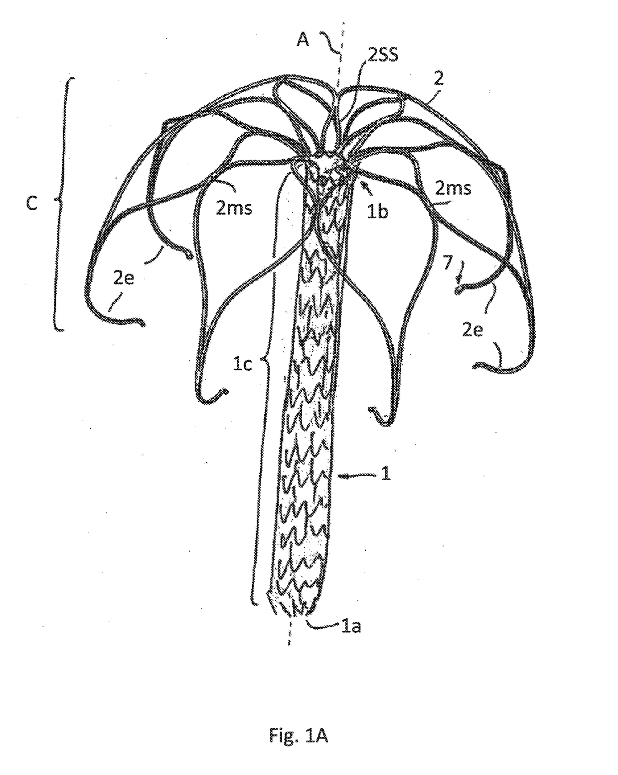
[0081]FIG. 1 show a first embodiment according to which the implant comprises a tubular attachment element 1 having a lower end 1a and an upper end 1b. The entire attachment element 1 is formed as a mesh by a radially expanded slotted tube, particularly as known from a typical stent construction. FIG. 1A just shows schematically the meshes of the meshed expanded tubular attachment element 1. FIG. 1B shows the attached sheath 1h, that in this drawing hides the underlying meshes, that serve as a supporting scaffold. Even though it is not shown the meshes may have a honeycomb shape.

[0082]A sheath 1h that is attached to the attachment element 1 may be formed of polymer fibers, by example as known by the trade name DACRON. The fibers may form a woven textile. Such sheath 1h serves to form the contact area for not closing leaflets of the natural valve of a diseased heard.

[0083]In this and all other possible embodiments of the invention described before and hereinafter the upper end 1b of ...


PUM


Abstract

The invention relates to a heart implant comprising a tubular attachment element (1) for attaching a sheath, particularly having a sheath being coaxially positioned around at least a part of the tubular attachment element (1) and fixed to it, the tubular attachment element (1) having a lower end (1a) and an upper end (1b) and being split into several strips (2) at the upper end (1b), the strips (2) forming an expandable cage (C), particularly for fixing the heart implant to the atrium of the heart by surface contact between an exterior surface of the expandable cage (C) and an interior atrium surface, wherein in an expanded state the strips (2) extend from the upper end (1b) towards the lower end (1a) of the tubular attachment element (1) and form an expanded cage (C) being positioned around at least an upper part of the tubular attachment element (1).

Description

TECHNICAL FIELD[0001]The invention relates to a heart implant, particularly a heart implant being configured to reduce or eliminate a heart valve insufficiency after implantation into the heart.BACKGROUND OF THE INVENTION[0002]Typically such implants are positioned in such a way that a closure element of the implant is situated in the valve annulus and closes a remaining gap of the closed valve leaflets. For that purpose the closure element is connected to an anchoring element being configured to fix the closure element within the heart in the desired position i.e. in the valve annulus preferably to be contacted by the closing valve leaflets.[0003]It is known in the art to use an anchoring element punctured into the myocardium of the ventricle for fixation of the closure element. Besides this invasive way modern implants provide a less invasive fixation just by contacting the interior wall of the atrium with the outer surface areas of an anchoring element formed of an expanded cage ...

Claims


Application Information

Patent Timeline
Patent Type & Authority Applications(United States)
IPC IPC(8): A61F2/24
CPCA61F2/246A61F2250/0003A61F2/2463A61F2230/0093
Inventor NATHE, NIKLAS MAXIMILIANBAR-ON, RAZMENZL, STAFAN DANIEL
Owner CORAMAZE TECH GMBH
Why Eureka
Try Eureka