
Drive unit for four-wheel drive vehicle

a four-wheel drive, drive unit technology, applied in the direction of engine-driven generators, battery/fuel cell control arrangements, transportation and packaging, etc., can solve the problems of affecting the operation of the vehicle, the structure or a design of the vehicle body will be restricted, and the driving power of the four-wheel drive vehicle will be restricted, so as to achieve efficient power generation

Active Publication Date: 2019-03-14
TOYOTA JIDOSHA KK
View PDF9 Cites 5 Cited by
  • Summary
  • Abstract
  • Description
  • Claims
  • Application Information

AI Technical Summary

Benefits of technology

The patent describes a device that efficiently generates electricity by using a first motor to driven the front wheels during deceleration. This helps to increase the grounding load of the front wheels and produces electricity. Additionally, the device includes a speed reducing device that reduces the rotational speed of the front propeller shaft in relation to the rotor shaft. This helps to improve the overall efficiency of the device.

Problems solved by technology

Due to the engine, the front drive motor, and the differential gear unit being thus disposed in a limited space in the central section in the vehicle width direction, there is a risk that a structure or a design of the vehicle body will be restricted.
However, since the torque driving the front wheels will be reduced, there is a risk that a driving power of the four-wheel drive vehicle will be restricted.
As a result, there is a risk that running stability or turning performance, and so on, of the vehicle body will worsen.

Method used


Image

  • Drive unit for four-wheel drive vehicle
  • Drive unit for four-wheel drive vehicle
  • Drive unit for four-wheel drive vehicle

Examples


Embodiment Construction

)

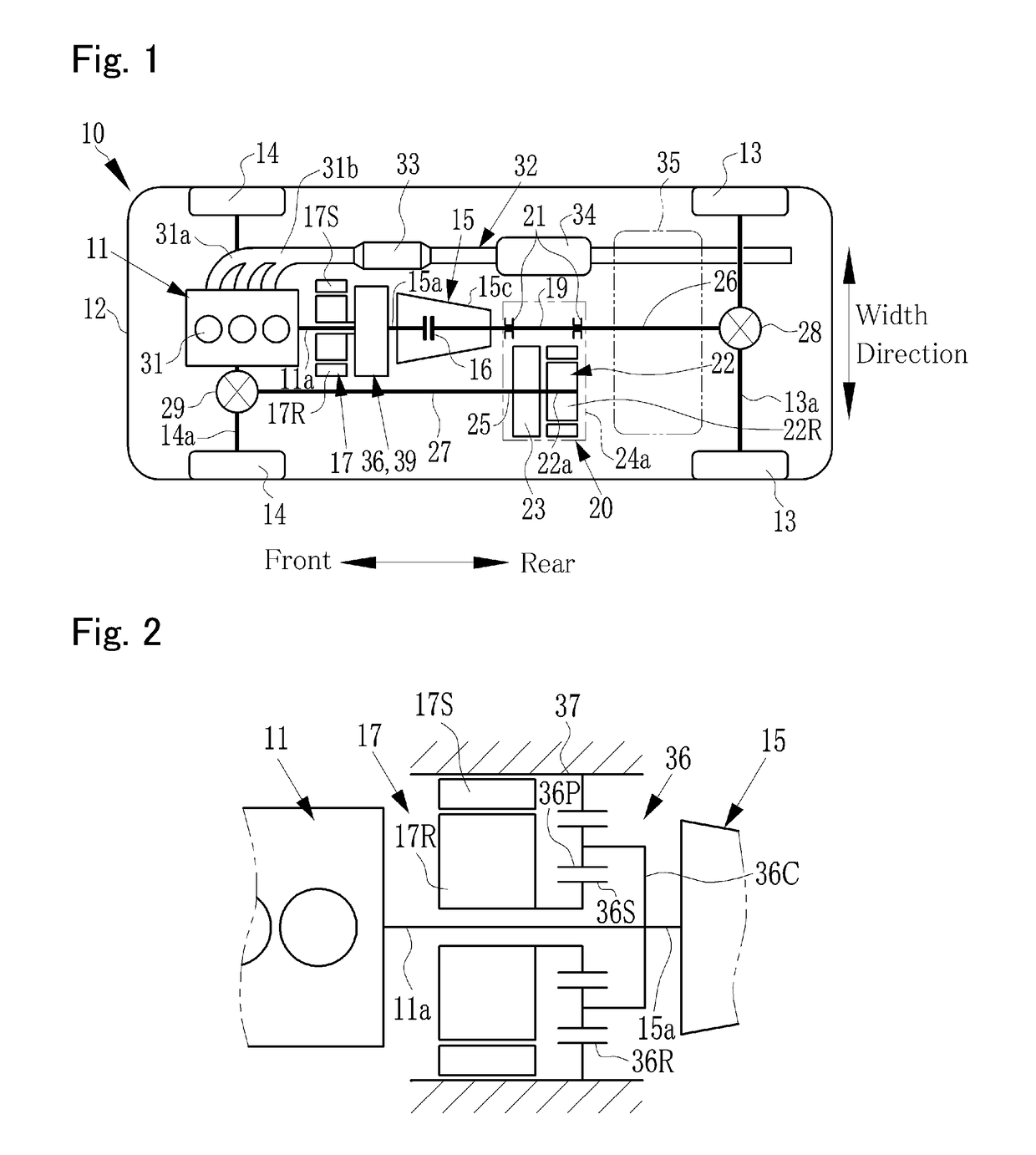
[0042]Embodiments of the present disclosure will now be explained with reference to the accompanying drawings. Turning now to FIG. 1, there is shown a powertrain of a four-wheel drive vehicle 10 according to at least one embodiment of the present disclosure. The vehicle 10 shown in FIG. 1 is a front-engine rear-drive layout four-wheel drive vehicle in which an engine 11 is disposed in a front side of a vehicle body 12, and a power of the engine 11 is transmitted to rear wheels 13. The engine 11 is disposed between left and right front wheels 14 in such a manner that an output shaft (or crankshaft) 11a extends in a front-rear direction of the vehicle body. In other words, the engine 11 is disposed in substantially a central section in a width direction of the vehicle body 12.

[0043]A transmission 15 as a main transmission is disposed on an output side of the engine 11, and the output shaft 11a of the engine 11 is connected to an input shaft 15a of the transmission 15. The likes of a ...


PUM


Abstract

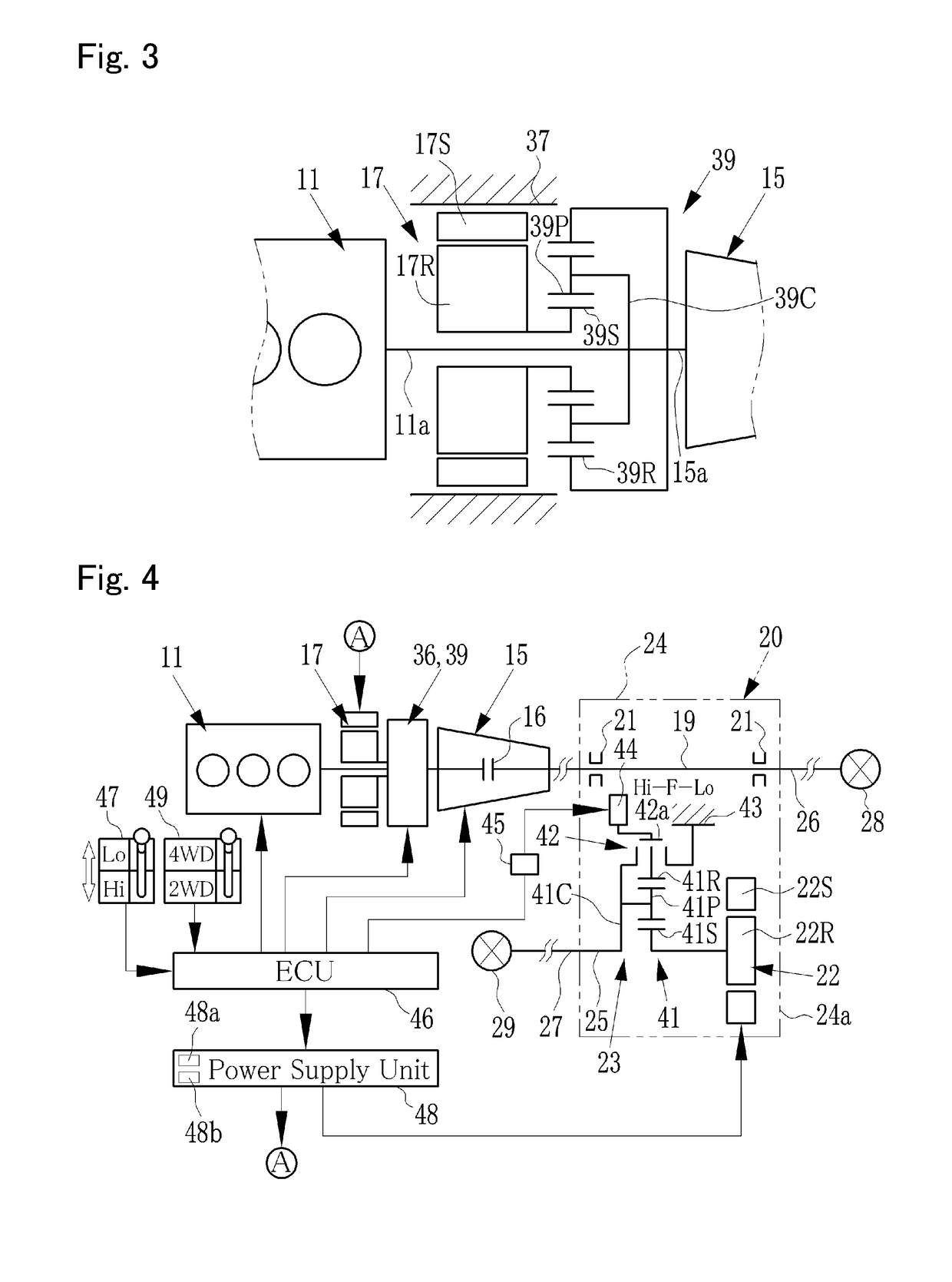
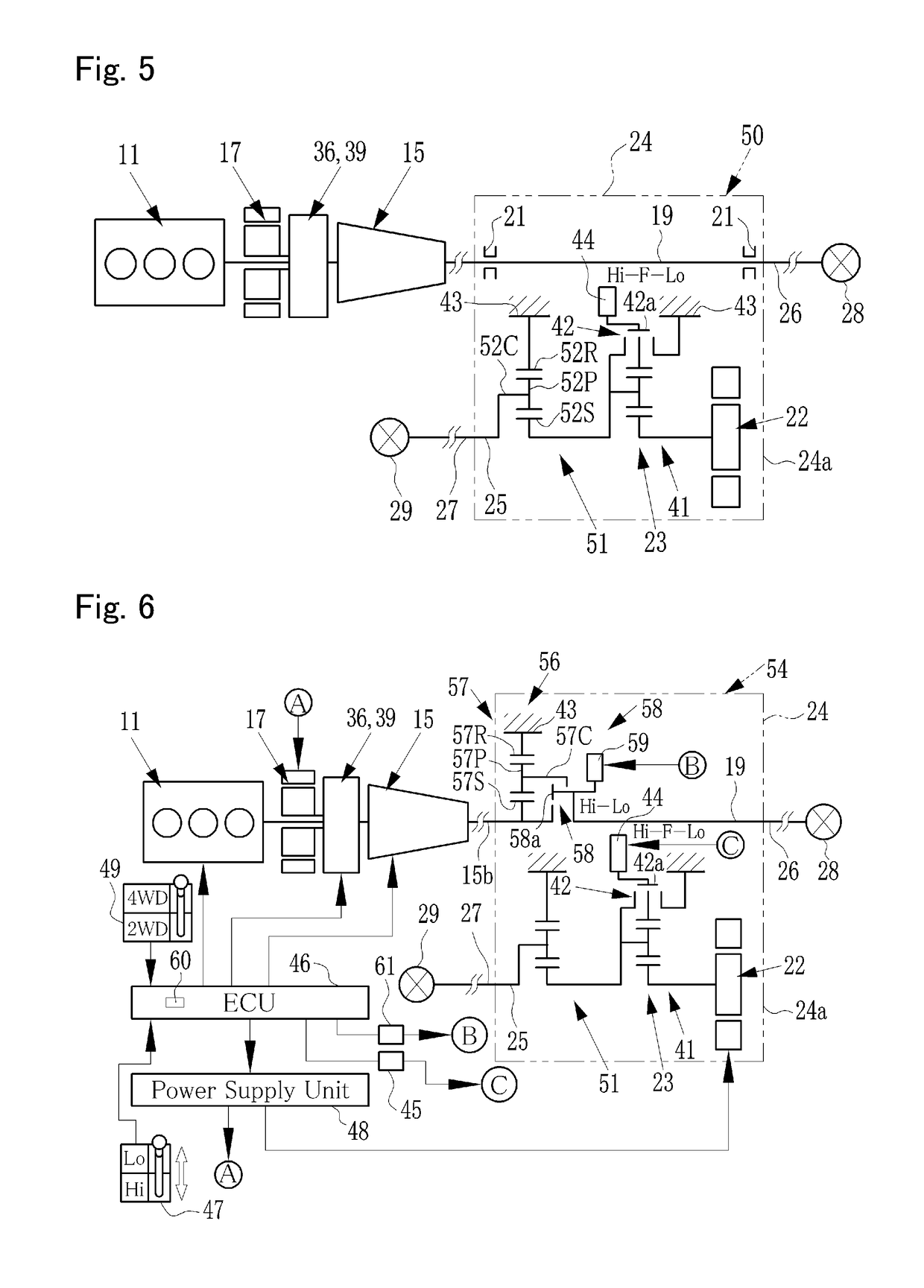
In a drive unit for four-wheel drive vehicle that allows a motor for driving front wheels to be easily installed, a torque of an engine is transmitted to a rear wheel axle via a transmission and a rear propeller shaft, and a torque of a front drive motor is transmitted to a front wheel axle via a front propeller shaft. A front drive unit is disposed between the transmission and the rear wheel axle. A case of the front drive unit houses: a main shaft that transmits to the rear propeller shaft an output torque of the transmission; the front drive motor; and a sub-shaft that is disposed in a position shifted in a vehicle width direction with respect to the main shaft and transmits to the front propeller shaft an output torque of the front drive motor.

Description

CROSS REFERENCE TO RELATED APPLICATIONS[0001]The present disclosure claims the benefit of Japanese Patent Application No. 2017-173144 filed on Sep. 8, 2017 with the Japanese Patent Office, the disclosure of which is incorporated herein by reference in its entirety.BACKGROUNDField of the Disclosure[0002]Embodiments of the present disclosure relate to the art of a drive unit for four-wheel drive vehicle in which a prime mover includes an engine and a motor or motor-generator, and by which the vehicle can run with the rear wheels powered by the engine and the front wheels powered by the motor.Discussion of the Related Art[0003]In a hybrid vehicle shown in FIG. 1 of JP-A-2016-2772, an engine, a rear drive motor that drives the rear wheels, and a transmission are arranged in order from the front side of the vehicle body, and a rear propeller shaft is connected to the transmission. In the hybrid vehicle described in JP-A-2016-2772, the engine drives the rear wheels, and a front drive moto...

Claims


Application Information

Patent Timeline
Patent Type & Authority Applications(United States)
IPC IPC(8): B60L5/10B60L11/14B60W10/08B60K6/485B60L11/18B60L15/20
CPCB60L5/10B60L11/14B60W10/08B60K6/485B60L11/1861B60L15/2009B60L2240/425B60L2260/28B60L2240/423B60L2240/421B60K6/24B60K6/26B60K6/365B60K6/38B60K6/40B60K6/442B60K6/52B60K6/387Y02T10/62Y02T10/72Y02T10/70B60L50/16B60L58/12
Inventor KUWAHARA, SEIJITAKADA, NORIFUMI
Owner TOYOTA JIDOSHA KK
Learn More