
System and method for low profile occlusion balloon catheter

a low-profile, balloon-type technology, applied in balloon catheters, medical science, surgery, etc., can solve the problems of sudden increase in blood flow across the balloon, vibration and pulse, and current technology utilizing a single-occlusion balloon with a smooth, continuous shape, etc., to achieve the effect of deescalating the vibrating and pulsing

Active Publication Date: 2019-03-14
PRYTIME MEDICAL DEVICES INC
View PDF0 Cites 8 Cited by
  • Summary
  • Abstract
  • Description
  • Claims
  • Application Information

AI Technical Summary

Benefits of technology

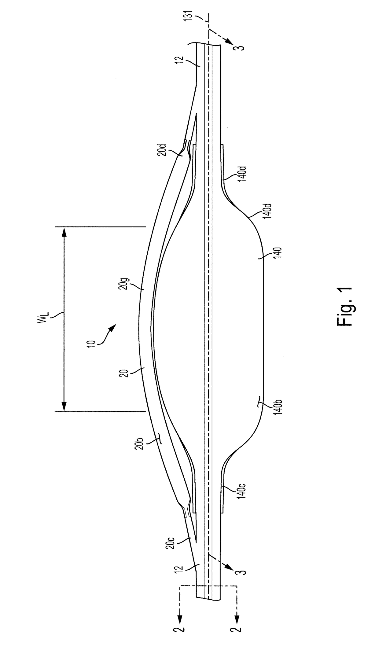
The preferred occlusion catheter system allows for full occlusion and smooth-controlled partial occlusion. It achieves this by creating flow paths for blood flow channels and maintaining constant contact between the balloon and the vessel wall during partial occlusion, which reduces vibrating and pulsing effects. Overall, this system provides better stability and control during partial occlusion procedures.

Problems solved by technology

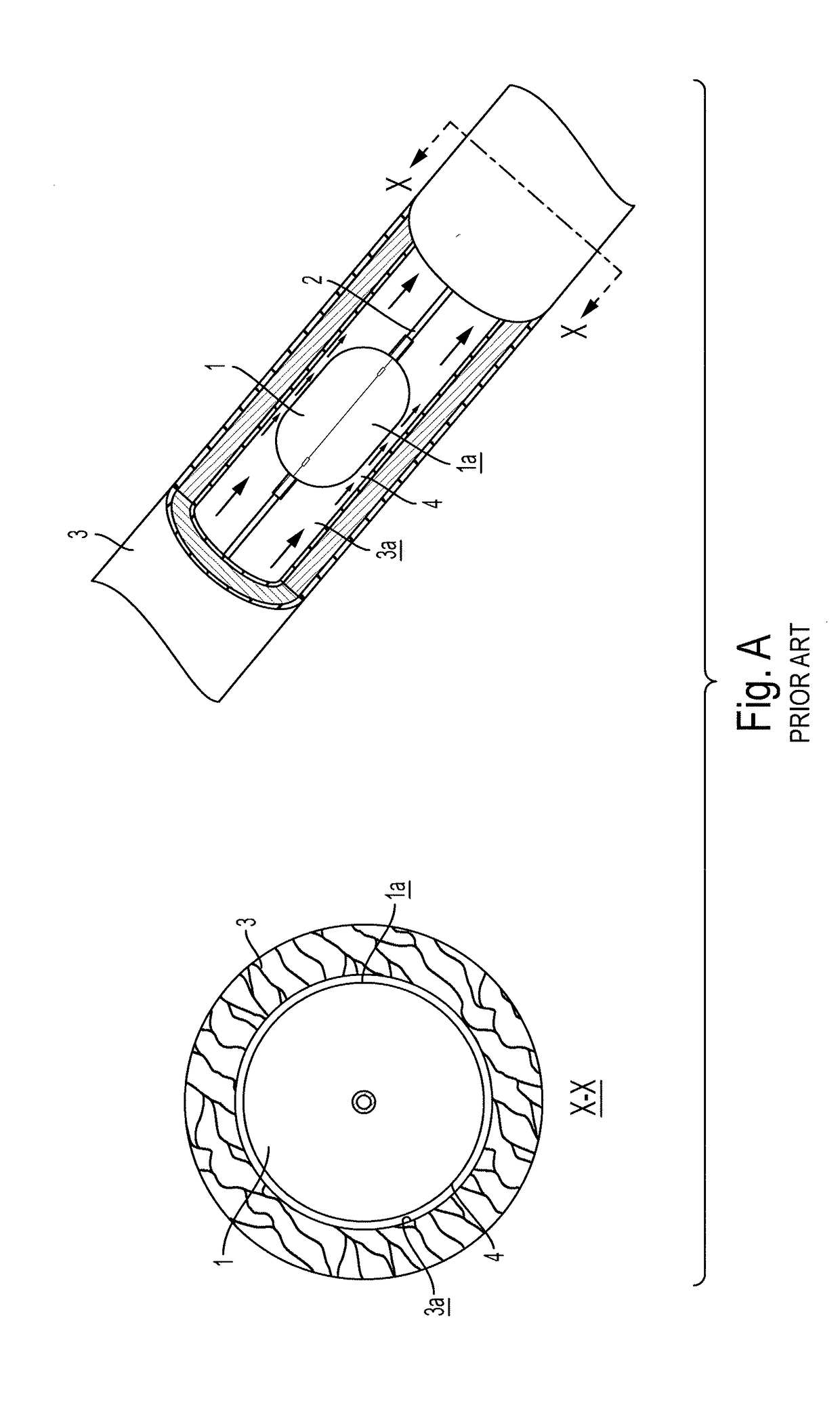
Current technology is limited in terms of partial occlusion because as the user withdraws fluid from the balloon to move from full occlusion to partial occlusion there is a sudden increase in blood flow across the balloon.
Current technology utilizing a single occlusion balloon with a smooth, continuous shape can become unstable, vibrate and pulse during partial occlusion because of minimal contact between the vessel wall and the external surfaces of the balloon.

Method used


Image

  • System and method for low profile occlusion balloon catheter
  • System and method for low profile occlusion balloon catheter
  • System and method for low profile occlusion balloon catheter

Examples


Embodiment Construction

[0086]Certain terminology is used in the following description for convenience only and is not limiting. Unless specifically set forth herein, the terms “a”, “an” and “the” are not limited to one element but instead should be read as meaning “at least one”. The words “right”, “left”, “lower” and “upper” designate directions in the drawings to which reference is made. The words “inwardly” or “distally” and “outwardly” or “proximally” refer to directions toward and away from, respectively, the patient's body, or the geometric center of the preferred occlusion catheter system and related parts thereof. The words, “anterior”, “posterior”, “superior,”“inferior”, “lateral” and related words and / or phrases designate preferred positions, directions and / or orientations in the human body or the device to which reference is made and are not meant to be limiting. The terminology includes the above-listed words, derivatives thereof and words of similar import.

[0087]It should also be understood t...


PUM


Abstract

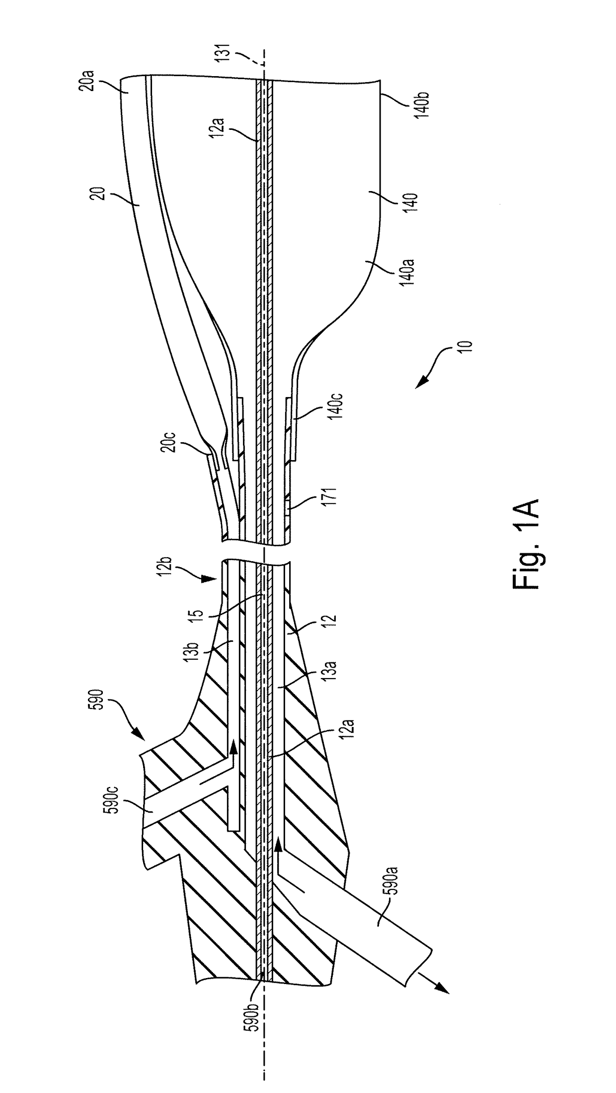
An occlusion catheter system includes an inflation catheter member and an occlusion balloon. The proximal and distal balloon ends are connected to the inflation catheter between the proximal and distal catheter ends. A distal pressure sensor is attached to the inflation catheter member between the proximal balloon end and the atraumatic tip. An inflatable spine is connected to the inflation catheter. The proximal spine end is connected to the inflation catheter near the proximal balloon end and the distal spine end is connected to the inflation catheter near the distal balloon end. The occlusion balloon and the inflatable spine are configured to define blood flow channels with the internal surface and the external balloon surface when the occlusion catheter system is at least partially positioned in the vessel and the occlusion balloon and the inflatable spine are in a partially inflated configuration.

Description

CROSS-REFERENCE TO RELATED APPLICATIONS[0001]The present application claims the benefit of U.S. Provisional Patent Application No. 62 / 375,472, filed on Aug. 16, 2016 and titled, “System and Method for Low Profile Occlusion Balloon Catheter,” U.S. Provisional Patent Application No. 62 / 344,699, filed on Jun. 2, 2016 and titled, “System and Method for Low Profile Occlusion Balloon Catheter” and U.S. Provisional Patent Application No. 62 / 353,388, filed Jun. 22, 2016 and titled, “System and Method for Low-Profile Occlusion Balloon Catheter,” the entire contents of which are incorporated herein by reference in their entirety.STATEMENT REGARDING FEDERALLY SPONSORED RESEARCH OR DEVELOPMENT[0002]This invention was made with government support under Contract No. W911QY-15-C-0099 awarded by U.S. Army Medical Materiel Agency. The government has certain rights in the invention.BACKGROUND OF THE INVENTION[0003]The present invention pertains generally to vascular occlusion catheters and methods of...

Claims


Application Information

Patent Timeline
IPC IPC(8): A61B17/12A61M25/10
CPCA61B17/12136A61B17/12036A61B17/12109A61M25/1002A61M25/104A61B2017/22055A61B2017/22051A61M25/0068A61M25/02A61M25/1011A61M2025/0002A61M2025/0003A61M2025/024A61M2025/028A61M2025/0286A61M2025/1052A61M2025/1056A61M2025/1061A61M2025/1084A61M2025/1088A61M2025/1095A61M25/10184A61M25/00A61M25/10
Inventor FRANKLIN, CURTIS J.KRUMMENACHER, TODD J.REYNOLDS, JEREMYSPENCER, DAVIDFISHER, LUKE WILLIAM
Owner PRYTIME MEDICAL DEVICES INC
Learn More