
Optical device and display device

a display device and optical technology, applied in optics, non-linear optics, instruments, etc., can solve the problems of complicated configuration of display devices, and achieve the effect of simple operation, simple configuration and simple configuration

Inactive Publication Date: 2019-02-28
FUJIFILM CORP
View PDF3 Cites 3 Cited by
  • Summary
  • Abstract
  • Description
  • Claims
  • Application Information

AI Technical Summary

Benefits of technology

The present invention provides an optical device and a display device that can switch between image display at a wide viewing angle and image display at a narrow viewing angle obtained by limiting the viewing angle using a simple operation without attaching or detaching any member. This optical device has a simple configuration and can be used in a tablet PC or notebook PC. The technical effects of this invention are stated in the patent text to solve the problems of related art.

Problems solved by technology

However, in the liquid crystal display device of JP2007-178979A, the configuration of the display device becomes complicated because the liquid crystal display element needs to have a special structure with W subpixels, a plurality of substrates, and a plurality of common electrodes and the liquid crystal display device needs to be driven in different modes.

Method used


Image

  • Optical device and display device
  • Optical device and display device
  • Optical device and display device

Examples


example 1

[0207]01>

[0208]The following materials were put into a mixing tank and stirred while being heated so that each component was dissolved, thereby preparing a cellulose acetate solution (dope) with the following composition.

[0209]>

[0210]Cellulose acetate (acetyl substitution degree of 2.86). . . 100 parts by mass

[0211]Triphenyl phosphate . . . 8 parts by mass

[0212]Biphenyl diphenyl phosphate . . . 4 parts by mass

[0213]Methylene chloride . . . 369 parts by mass

[0214]Methanol . . . 80 parts by mass

[0215]1-Butanol . . . 4 parts by mass

[0216]The prepared dope was heated to 30° C. and allowed to pass through a casting geeser so that the dope was cast on a glass plate. The surface temperature of the glass was set to −5° C., and the space temperature of the entire casting portion was set to 15° C.

[0217]After the casting, the dope was allowed to stand for 1 minute, dried at 45° C. for 1 minute, and peeled off from the glass. Next, the resultant was dried at 110° C. for 5 minutes and further dr...

example 2

[0266]01>

[0267]1.11 g of an initiator solution [a solution obtained by dissolving 0.90 g of IRGACURE 907 (manufactured by BASF SE) and 0.30 g of KAYACURE DETX (manufactured by Nippon Kayaku Co., Ltd.) in 8.80 g of methyl ethyl ketone (MEK)] was added to a liquid crystal solution obtained by dissolving 3.04 g of a liquid crystal compound (PALIOCOLOR LC242 (trade name), manufactured by BASF SE) containing a photopolymerizable group and 0.1 g of a polymeric surfactant (MEGAFACE F780F, manufactured by DIC Corporation) in 5.07 g of methyl ethyl ketone (MEK), and the solution was stirred for 5 minutes for complete dissolution.

[0268]Next, 0.023 g of a dichroic azo coloring agent G241 (manufactured by HAYASHIBARA CO., LTD.) and 0.005 g of a dichroic azo coloring agent G472 (manufactured by HAYASHIBARA CO., LTD.) were added to the obtained solution and subjected to ultrasonic dispersion for 5 minutes, thereby preparing a polarizing film coating solution.

[0269]

[0270]The following materials ar...


PUM

PropertyMeasurementUnit
viewing angleaaaaaaaaaa
angleaaaaaaaaaa
wavelengthaaaaaaaaaa

Abstract

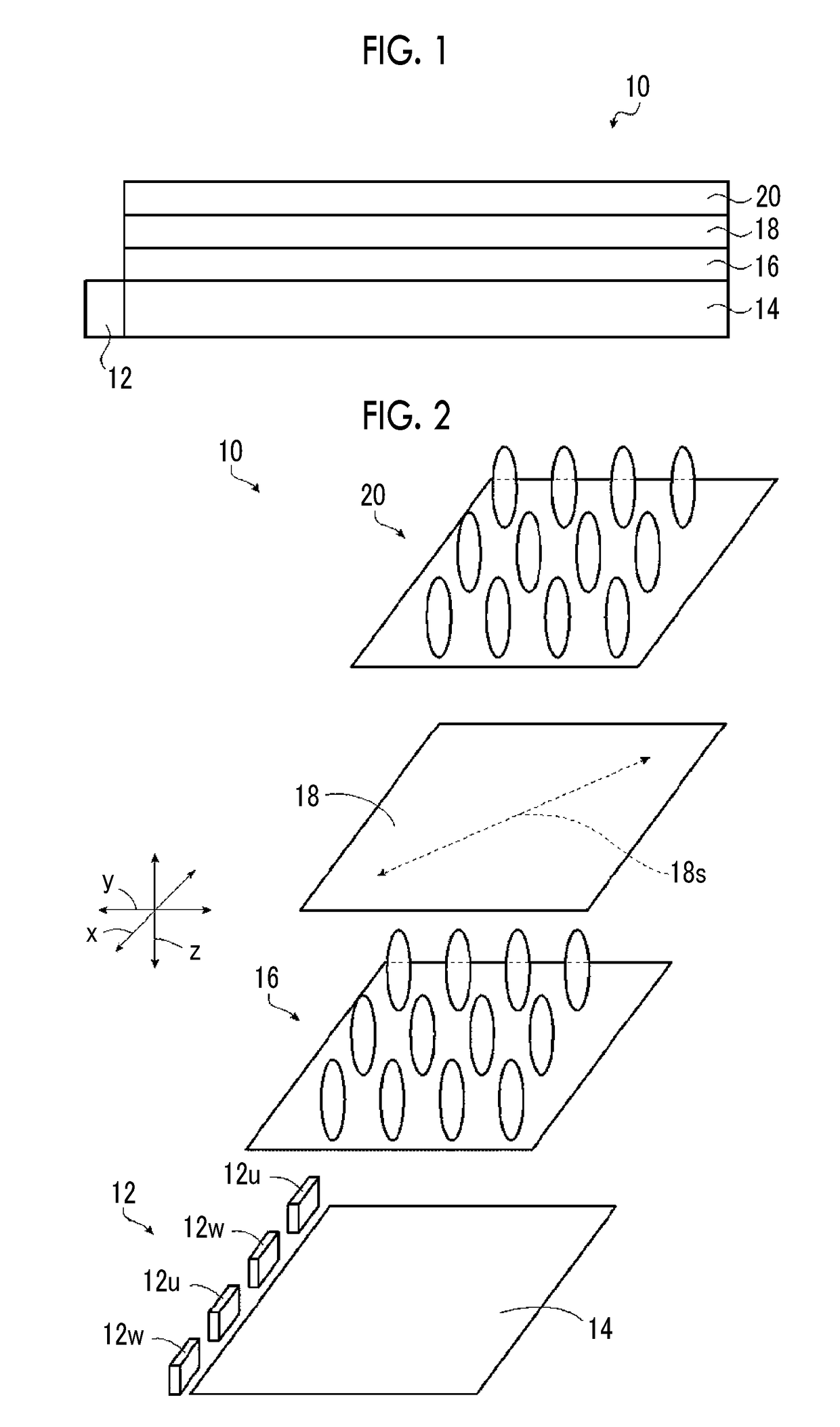
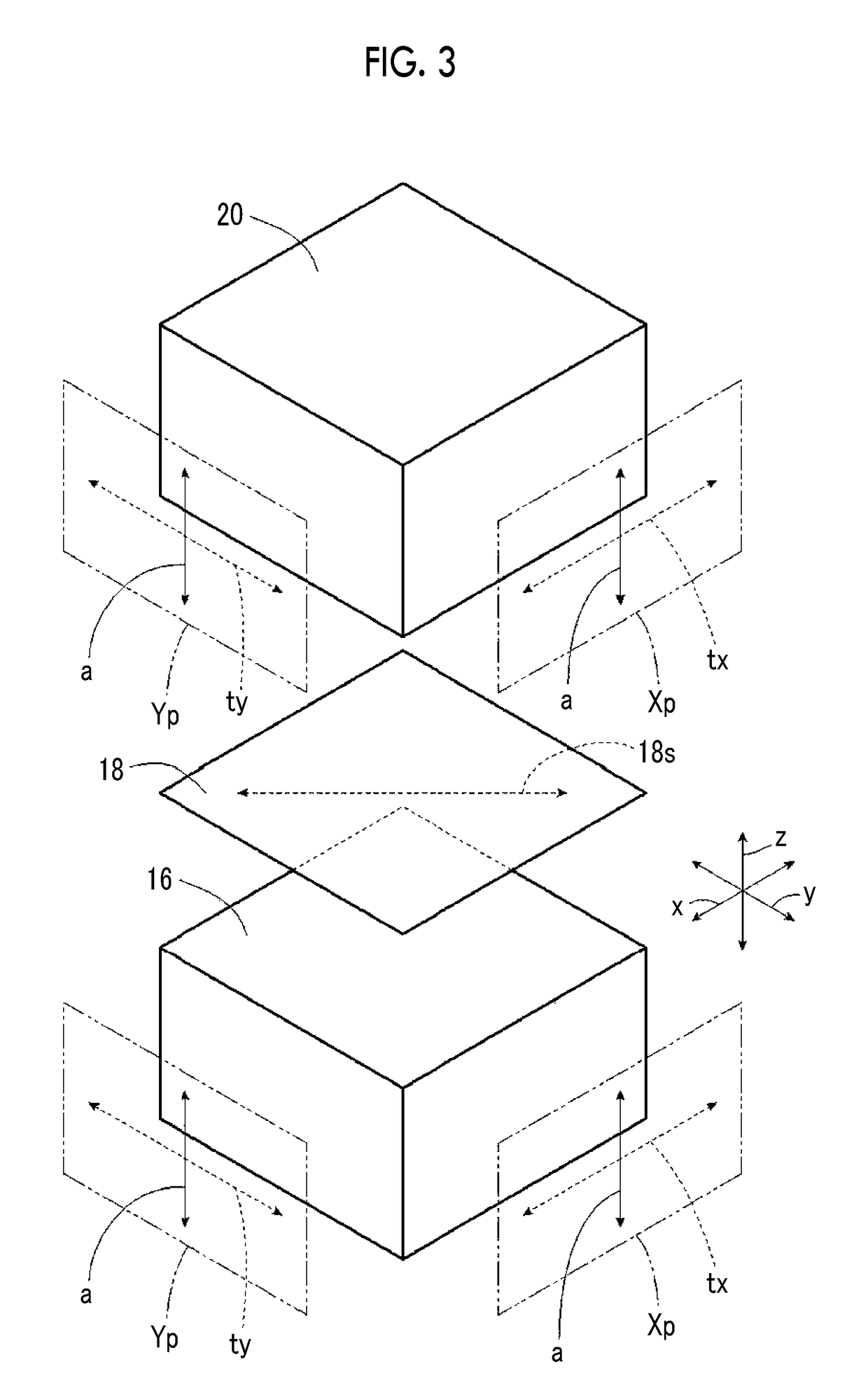
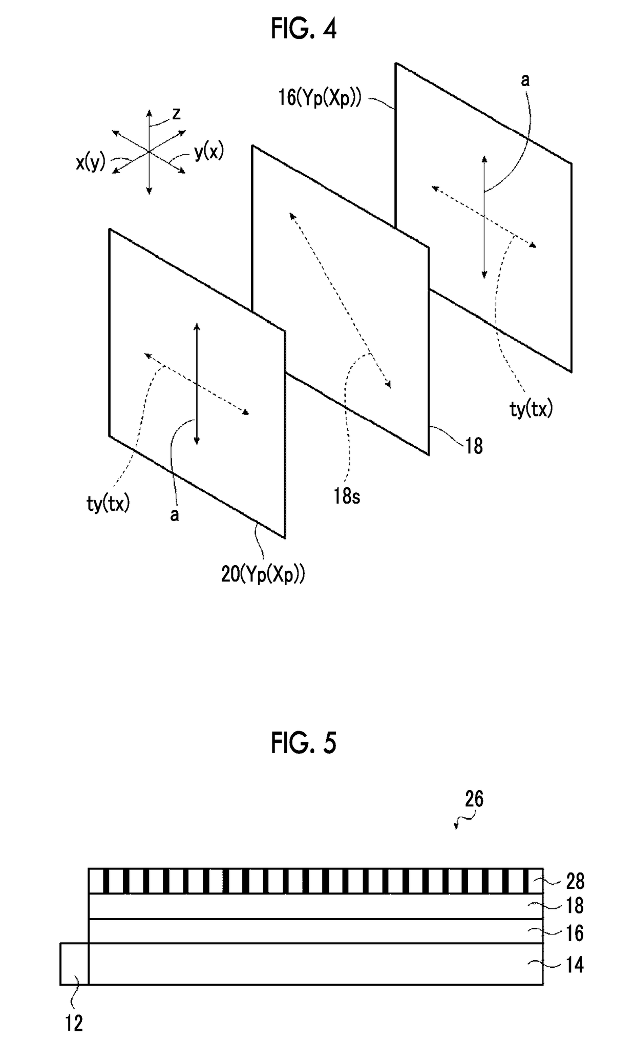
An optical device includes a first composite film; a second composite film or a polarizing film; a λ / 2 plate; and a light-emitting unit, in which the first composite film and the second composite film contains a liquid crystal compound aligned in a thickness direction and a photochromic material, optical characteristics of the photochromic material are changed by irradiation with light, a light transmittance in the thickness direction becomes smaller than a light transmittance in a direction orthogonal to the thickness direction, the polarizing film has an absorption axis in the thickness direction, and the light-emitting unit emits light that changes the optical characteristics of the photochromic material.

Description

CROSS-REFERENCE TO RELATED APPLICATIONS[0001]This application is a Continuation of PCT International Application No. PCT / JP2017 / 015221, filed on Apr. 14, 2017, which claims priority under 35 U.S.C. § 119(a) to Japanese Patent Application No. 2016-101961, filed on May 20, 2016. Each of the above application(s) is hereby expressly incorporated by reference, in its entirety, into the present application.BACKGROUND OF THE INVENTION1. Field of the Invention[0002]The present invention relates to an optical device used for a display device such as a liquid crystal display device and a display device using this optical device.2. Description of the Related Art[0003]In personal electronic devices, for example, tablet personal computers (PCs), notebook PCs, and mobile phones such as smartphones, there is a demand that users do not want their screens to be peeped by the surrounding third parties. Therefore, in these electronic devices, it has been attempted to narrow the viewing angle of a scre...

Claims


Application Information

Patent Timeline
Patent Type & Authority Applications(United States)
IPC IPC(8): G02F1/13G02F1/1335G02F1/1347G02F1/13363
CPCG02F1/1323G02F1/133617G02F1/1347G02F1/13363G02F2201/44G02F2203/05G02F1/13725G02F2001/13775G02F2001/133742G02F2001/133638G02F2413/08G02F2413/01G02F2001/133626G02B5/23G02B5/3016G02F1/13362G02F2202/14G02F1/133633G02F1/133638G02F1/133531G02F1/133626G02F1/133742G02F1/13775
Inventor YANAI, YUJIRO
Owner FUJIFILM CORP
Learn More