Non-contact and optical measuring automation system for the profile accuracy of disk cams and method thereof

a technology of automation system and disk cam, which is applied in the direction of optically investigating flaws/contamination, measuring devices, instruments, etc., can solve the problems of deviation from the prescribed position, slight measurement error, and deformation of the probe or anvil of the measuring devi

Active Publication Date: 2019-02-28
NATIONAL TAIWAN OCEAN UNIVERSITY
View PDF0 Cites 9 Cited by
  • Summary
  • Abstract
  • Description
  • Claims
  • Application Information

AI Technical Summary

Benefits of technology

The patent describes a system and method for measuring the accuracy of a disk cam using a non-contact and optical measuring automation system. The system includes a laser displacement meter and a rotating chuck for clamping the disk cam. The method involves inputting theoretical profile information of the disk cam, setting a measuring parameter, and executing a measuring procedure by the laser displacement meter. The system and method allow for accurate measurement of the disk cam's profile accuracy.

Problems solved by technology

When the manufacturing error of the cam profile exceeds its allowable tolerance, the positioning accuracy of the follower, in contact with the cam, will be influenced by the cam and thus deviates from its prescribed position.
Furthermore, the dynamic performance of the cam mechanism will also be influenced so as to produce excessive vibration and noise in high-speed operations.
The probe or anvil of the measuring device may slightly deform due to the force acting in contact with the measured cam profile, and such a situation may result in slight measuring error as well as the wear of the probe or the anvil.
However, the conventional measuring device and method can be applied to a disk cam with a geometric feature of convex profile but cannot be applied to a disk cam with a geometric feature of concave profile.
More specifically, when the concave profile of the disk cam rotates to an angular position for being measured, the parallel light beam emitted from the measuring device cannot project onto the hollow part of the concave profile, so that the profile deviation of the hollow part cannot be measured.

Method used


Image

  • Non-contact and optical measuring automation system for the profile accuracy of disk cams and method thereof
  • Non-contact and optical measuring automation system for the profile accuracy of disk cams and method thereof
  • Non-contact and optical measuring automation system for the profile accuracy of disk cams and method thereof

Examples


first embodiment

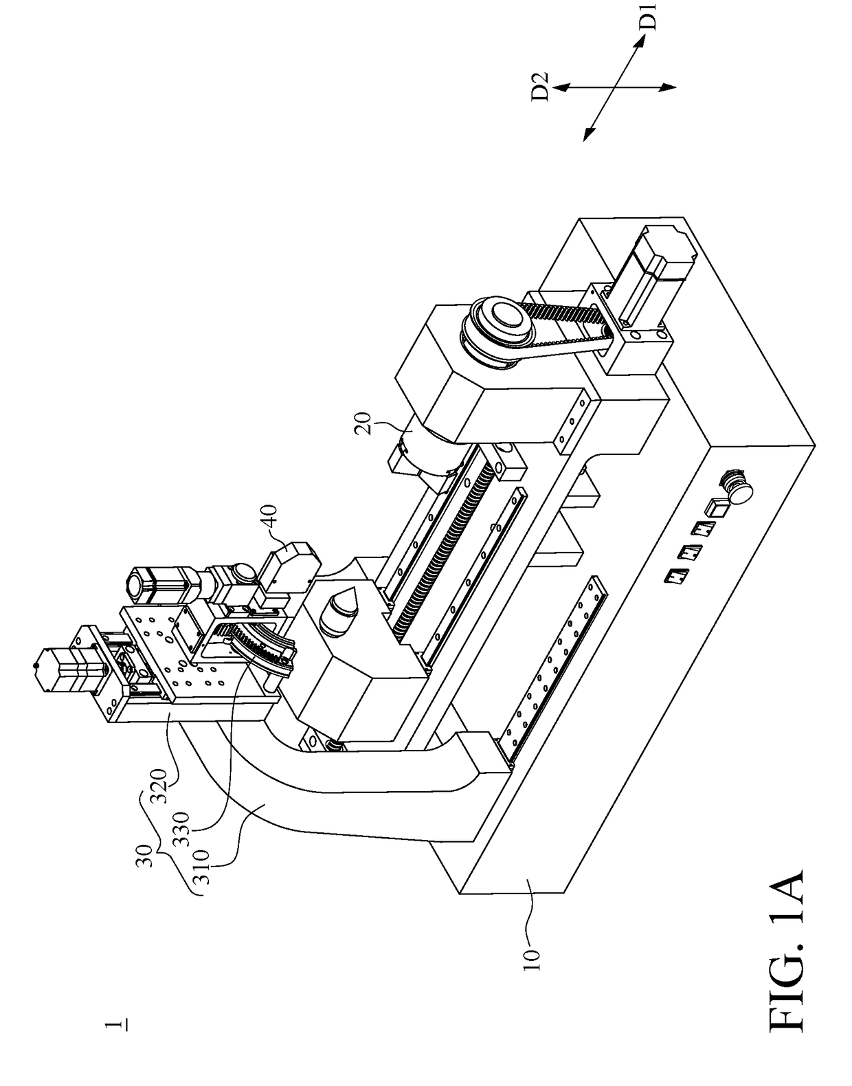
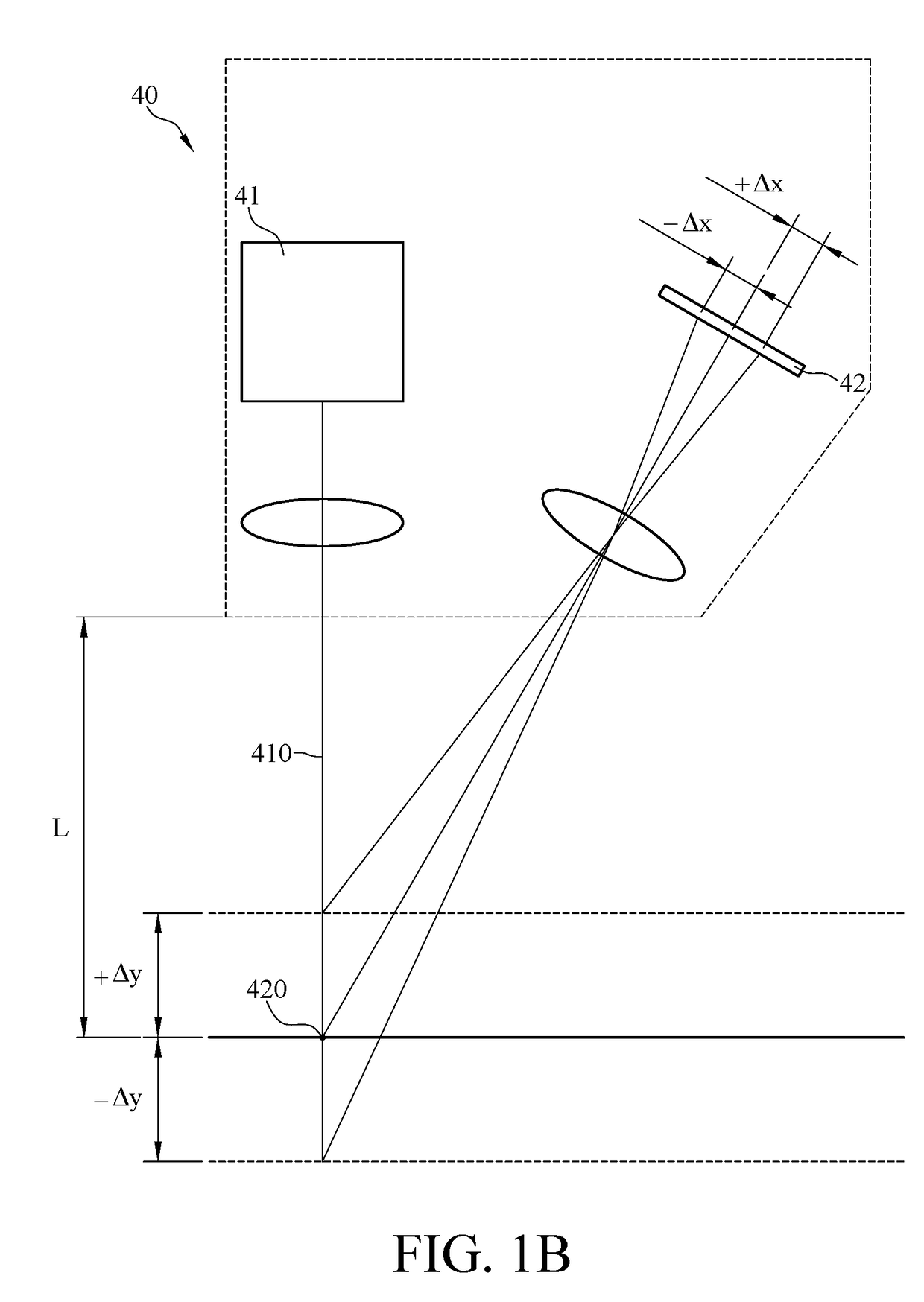
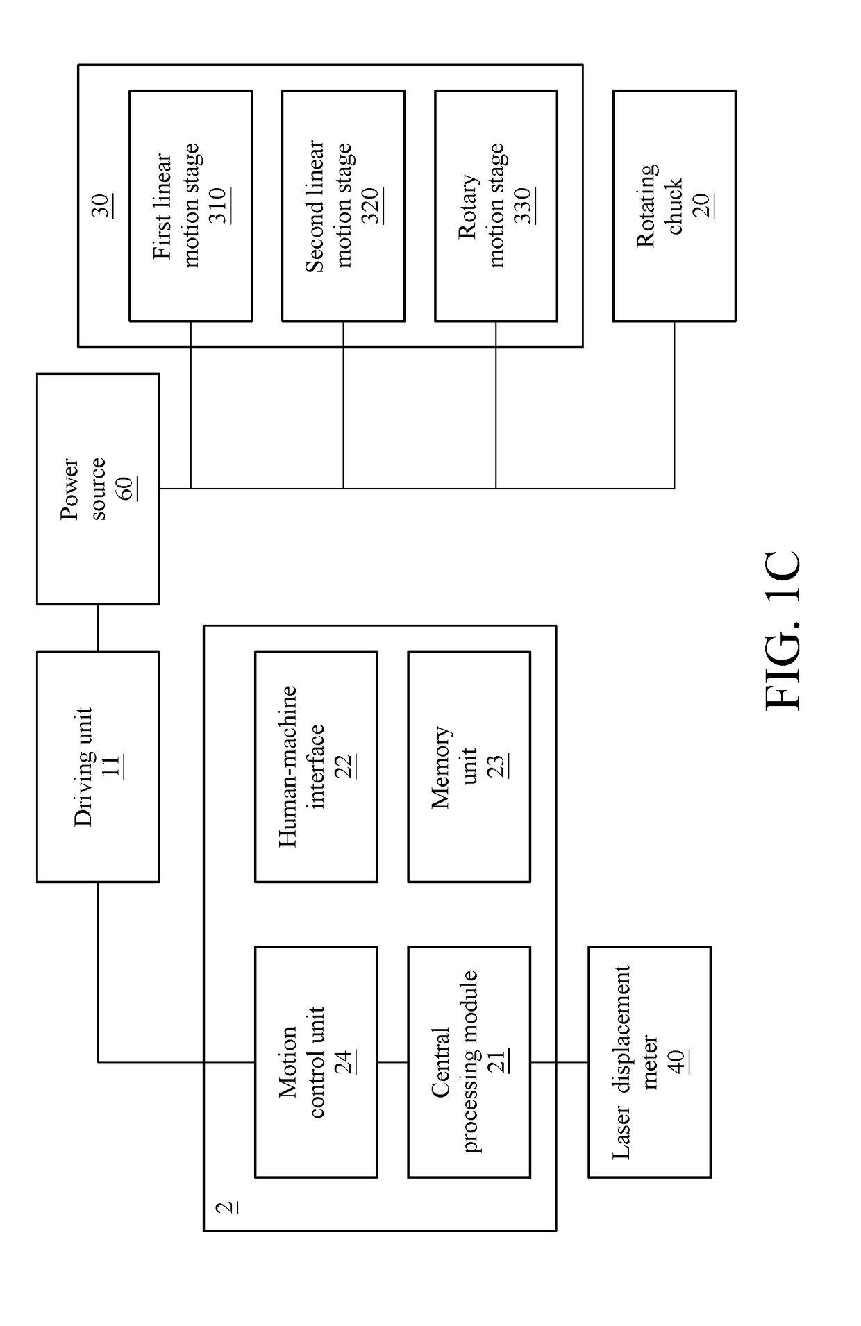
[0022]Please refer to FIG. 1A to FIG. 3B. FIG. 1A is a perspective view of a non-contact and optical measuring automation system according to this disclosure. FIG. 1B is a schematic diagram of a laser triangulation method. FIG. 1C is a block diagram of the non-contact and optical measuring automation system in FIG. 1A and a computer. FIG. 2 is a schematic breakdown drawing of the non-contact and optical measuring automation system in FIG. 1A. FIG. 3A is a perspective view of the rotary motion stage of the moving stage module in FIG. 2. FIG. 3B is an exploded view of the rotary motion stage in FIG. 3A. This embodiment provides a non-contact and optical measuring automation system 1 which measures the profile accuracy of a disk cam by an automatic and non-contact method. The non-contact and optical measuring automation system 1 includes a base 10, a rotating chuck 20, a moving stage module 30 and a laser displacement meter 40.

[0023]The rotating chuck 20 is disposed on the base 10 and ...

second embodiment

[0060]The second embodiment provides a non-contact and optical measuring automation system 1a. The moving stage module 30 of the non-contact and optical measuring automation system 1a comprises a first linear motion stage 310 and a second linear motion stage 320 but does not comprise a rotary motion stage.

[0061]As shown in FIG. 7, in the non-contact and optical measuring method of the second embodiment, after the step S41 is completed, the step S44a is directly executed without the steps S42 and S43 described in the first embodiment, so as to obtain the first radial profile deviation value, and then the step S44b is executed. In the step S44b, the computer 2 can conduct calculation based on a relational expression for the cam profile deviation and the first radial profile deviation value measured in the step S44a, so as to obtain an approximate solution of the first normal profile deviation value with sufficient accuracy. The said relational expression for the cam profile deviation ...


PUM


Abstract

A non-contact and optical measuring automation system, configured to electrically connect to a computer to measure the profile accuracy of a disk cam, includes a base, a rotating chuck, a moving stage module and a laser displacement meter. The rotating chuck is disposed for clamping the disk cam. The moving stage module includes a first linear motion stage movable relative to the base in a first direction and a second linear motion stage movable relative to the first linear motion stage in a second direction. The computer is able to control the rotation of the rotating chuck and the movement of the moving stage module, and is able to control a beam emitted from the laser displacement meter projecting onto a profile surface of the disk cam so as to obtain a profile deviation value of the disk cam by using the laser triangulation method.

Description

CROSS-REFERENCE TO RELATED APPLICATIONS[0001]This non-provisional application claims priority under 35 U.S.C. § 119(a) on Patent Application No(s). 106129071 filed in Taiwan, R.O.C. on Aug. 25, 2017, the entire contents of which are hereby incorporated by reference.BACKGROUNDTechnical Field[0002]This disclosure relates to a measuring automation system and measuring method for the profile accuracy of a disk cam, and particularly to an optical measuring automation system and measuring method for measuring the profile accuracy in a non-contact manner.Related Art[0003]Cams are mechanical components commonly used in various machines and automation equipment. The cam makes its follower to produce a prescribed motion through direct contact in order to achieve required motion control. Generally, a disk cam is machined by using computer numerical control (CNC) machines to cut and grind its cam shape in order to obtain an accurate cam profile. When the manufacturing error of the cam profile e...

Claims


Application Information

Patent Timeline
IPC IPC(8): G01B11/26G01N21/47G01N21/89F16H53/00
CPCG01N21/4788G01N21/8901F16H53/00G01N2021/479G01B11/26G01B11/0608G01B11/24
Inventor CHANG, WEN-TUNGLU, CHUN-CHENGKAO, HSIANG-LUN
Owner NATIONAL TAIWAN OCEAN UNIVERSITY
Why Eureka
Try Eureka