Microelectromechanical integrated sensor structure with rotary driving motion
a microelectromechanical and integrated sensor technology, applied in the direction of acceleration measurement using interia force, speed measurement using gyroscopic effects, devices using electric/magnetic means, etc., can solve the problems of limited configurability and unsatisfactory gyroscopes of a known type, and achieve high detection efficiency and configurability, and simple manufacturing
- Summary
- Abstract
- Description
- Claims
- Application Information
AI Technical Summary
Benefits of technology
Problems solved by technology
Method used
Image
Examples
first embodiment
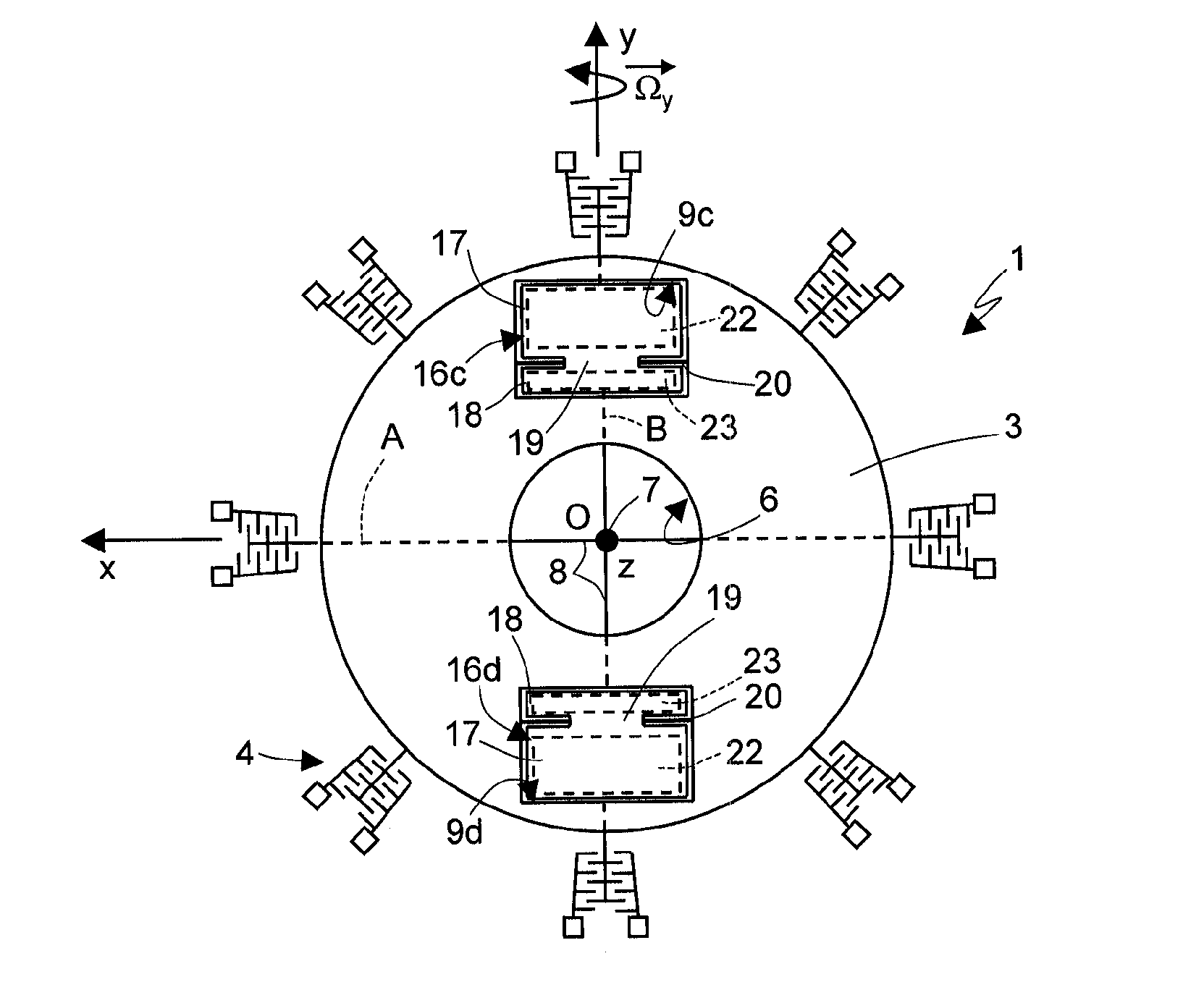
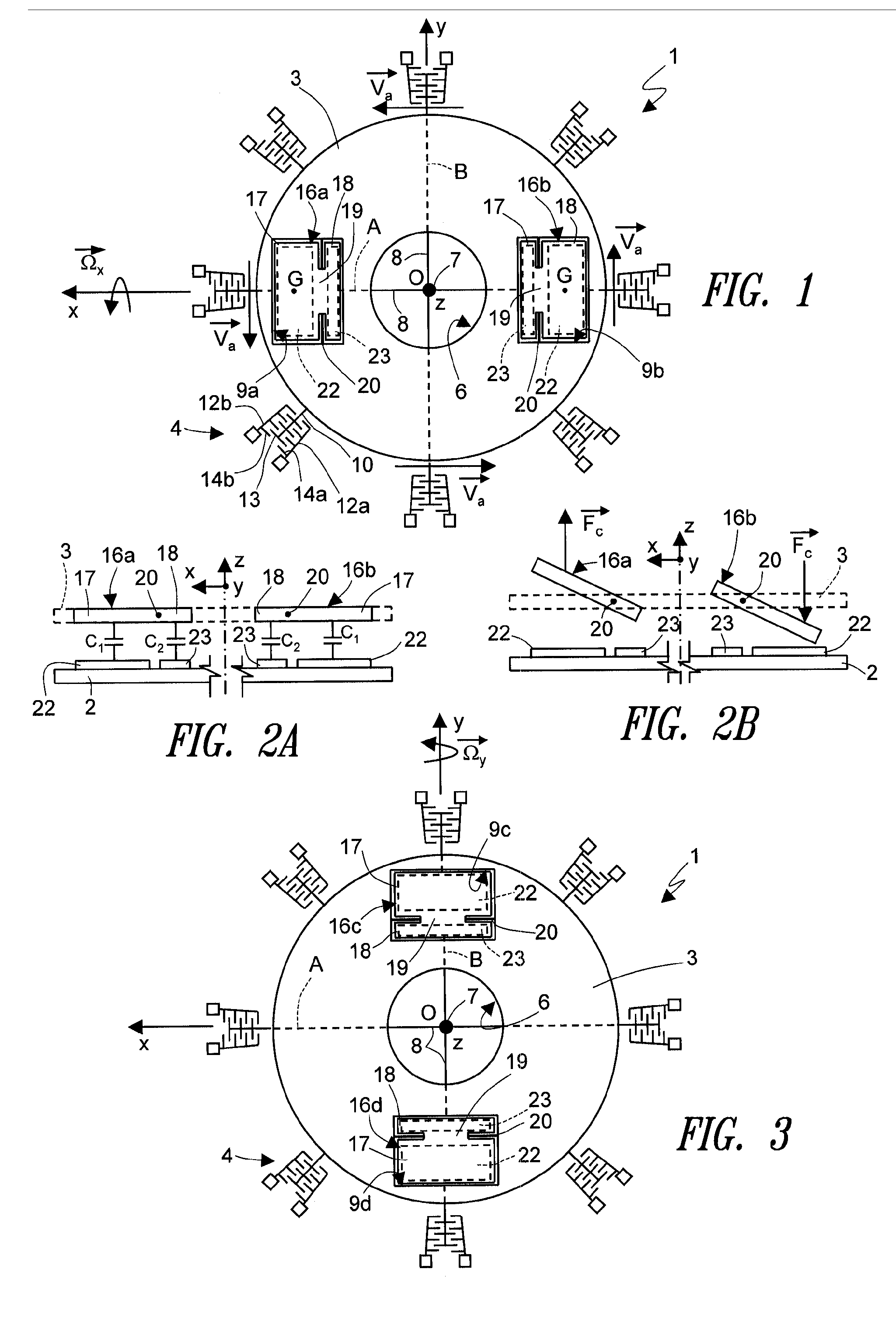
[0029] In detail, and with initial reference to FIG. 1, a microelectromechanical sensor structure 1 according to the invention comprises a driving structure formed by a driving mass 3 and by a driving assembly 4. The driving mass 3 has, for example, a generally circular geometry with radial symmetry (other geometries are in any case possible), with a substantially planar configuration having a main extension in a plane defined by a first axis x and by a second axis y (referred to in what follows as “plane of the sensor xy”), and negligible dimension, with respect to the main extension, in a direction parallel to a third axis (referred to in what follows as “orthogonal axis z”), forming with the first and second axes x, y a set of three orthogonal axes fixed with respect to the sensor structure. In particular, the driving mass 3 has in the plane of the sensor xy substantially the shape of an annulus, and defines at the centre an empty space 6, the centre 0 of which coincides with the...
third embodiment
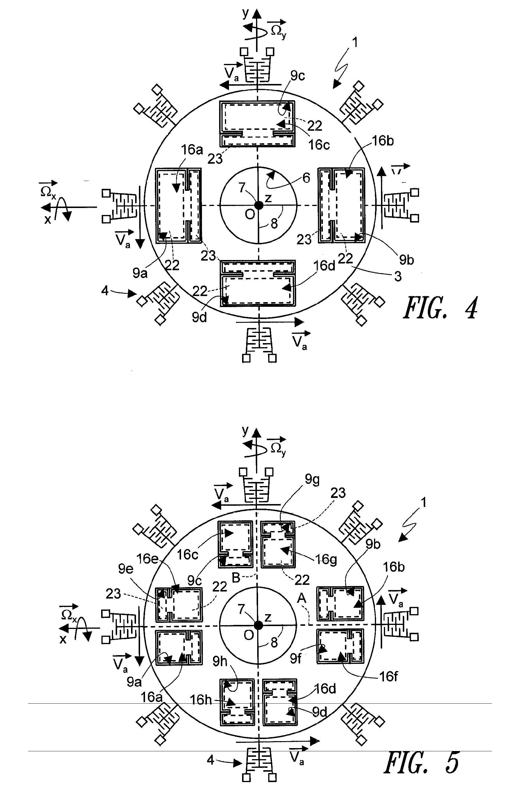
[0041] In order to solve said problem, the invention (shown in FIG. 5), envisages use of a further pair of acceleration sensors with axis parallel to the orthogonal axis z, and hence of first sensing masses for each axis of detection (for a total of eight first sensing masses in the case of a biaxial gyroscope). The microelectromechanical sensor structure 1 comprises in this case: a third pair of first sensing masses 16e, 16f, which co-operate with the first pair of first sensing masses 16a, 16b in detecting angular accelerations about the first axis x and are housed in a third pair of first through openings 9e, 9f; and a fourth pair of first sensing masses 16g, 16h, which co-operate with the second pair of first sensing masses 16c, 16d in detecting angular accelerations about the second axis y and are housed in a fourth pair of first through openings 9g, 9h. In a way similar to what has been previously described, corresponding to the third and fourth pairs of sensing masses are a t...
fourth embodiment
[0050] the present invention envisages a microelectromechanical structure sensing angular velocities about the orthogonal axis z. Said structure is similar to the ones described previously (so that parts that are similar will be designated by the same reference numbers), but differs as regards the arrangement of the sensing masses (and the movement that these may be allowed by the elastic supporting elements) and as regards the adopted principle of detection. In particular, in this case, through openings made in the driving mass 3 acceleration sensors are provided with axis lying in the plane of the sensor xy (for example, with their axis parallel to the first or to the second axis x, y).
[0051] In detail (see FIG. 11), the microelectromechanical sensor structure 1 comprises a pair of accelerometers with axis lying in the plane of the sensor xy, and in particular a first pair of second sensing masses 25a, 25b set within a first pair of second through openings 26a, 26b. The second thr...
PUM
 Abstract
Description
Claims
Application Information
 - R&D
- Intellectual Property
- Life Sciences
- Materials
- Tech Scout
- Unparalleled Data Quality
- Higher Quality Content
- 60% Fewer Hallucinations
Browse by: Latest US Patents, China's latest patents, Technical Efficacy Thesaurus, Application Domain, Technology Topic, Popular Technical Reports.
© 2025 PatSnap. All rights reserved.Legal|Privacy policy|Modern Slavery Act Transparency Statement|Sitemap|About US| Contact US: help@patsnap.com


