Dynamic Electric Drive Control

a technology of electric drive and control circuit, which is applied in the direction of electric propulsion mounting, electric propulsion cycles, transportation and packaging, etc., can solve the problems of limiting factors, substantial time spent at low efficiencies, and poor efficiency curve, so as to maximize system efficiency, improve performance, and improve the effect of efficiency

Inactive Publication Date: 2019-02-28
JACKSON BRITT +1
View PDF4 Cites 1 Cited by
  • Summary
  • Abstract
  • Description
  • Claims
  • Application Information

AI Technical Summary

Benefits of technology

This patent describes a new type of electric vehicle (EV) that uses two motors to help distribute power and optimize efficiency. The motors can be adjusted to work together or separately, depending on the road conditions, to make the most use of power. This design provides better performance and more precise control over power levels, allowing components to meet regulations and perform well. Overall, this patent presents a new way to improve efficiency and performance of EVs.

Problems solved by technology

The limitation of such motors is that they exhibit an efficiency curve which demonstrates poor efficiency at low RPM.
As a result, when LEVs operate over a wide RPM operating range, substantial time is spent at low efficiencies.
However, as load also increases, the controller supplies more amperage until it reaches the maximum amperage supported by system components, thus amperage can become a limiting factor.
Under heavy loads (either cargo, slope or wind resistance) the only real option is to inefficiently pump amperage into the system.
Unfortunately, increasing amperage creates heat which wastes energy.
While it is possible to increase the power rating of the motor or battery to mediate this inefficiency under load, some jurisdictions have specific limitations on the rated power of the LEV drive system.
However, the low speed efficiency of a geared motor compromises efficiencies at the higher speeds required by the application.
Creation of a single motor which provides low speed torque and high speed efficiency is either impossible or costly.
Each of these add cost, complexity, and failure modes and have limitations specific to their application.
While this does provide “post-traction” it ultimately multiplies the inefficiencies of single motors.

Method used


Image

  • Dynamic Electric Drive Control
  • Dynamic Electric Drive Control
  • Dynamic Electric Drive Control

Examples


first embodiment

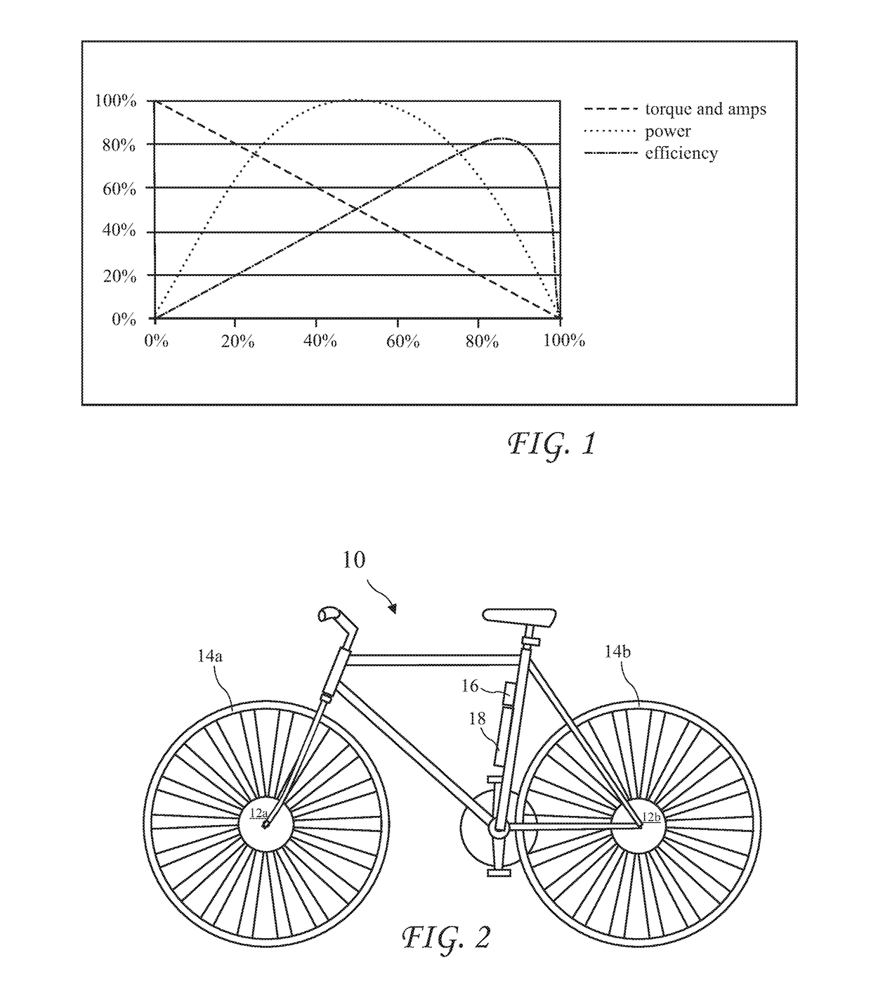
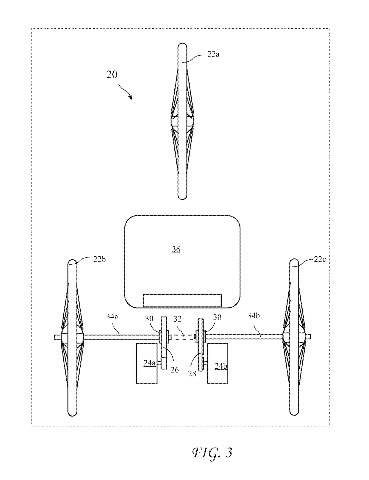
[0025]FIG. 2 shows a bicycle 10 having 10 electric motors 12a and 12b (for example, hub motors), the first motor 12a driving a front wheel 12a, and a second motor 12b independently driving a rear wheel 12b. The two electric motors 12a and 12b allow for the rear motor 12b to be geared for more torque and lower speed (creating a “first gear”) and the front motor 12a to be geared for higher speed with greater efficiency (creating a “second gear”). A processor (or controller) 16 monitors rider inputs (for example, throttle position, pedal torque, brake application, etc.) and vehicle data (for example, motor efficiency and vehicle speed and acceleration) and determines how to most efficiently power the bicycle 10 using a battery 18 providing current and voltage to the motors 12a and 12b. The controller may further have stored efficiency versus RPM data for the motors 12a and 12b. Overlapping the motors 12a and 12b with different applications of primary power (both current and voltage) al...

second embodiment

[0026]Alternately, motors can be connected to the wheels or axles through gears, chains or belts. When separate motors provide torque to right and left wheels of a three or four wheeled vehicle, an additional software function is incorporated to blend power on start up so that the low speed wheel doesn't receive so much power that it begins to steer the vehicle.

third embodiment

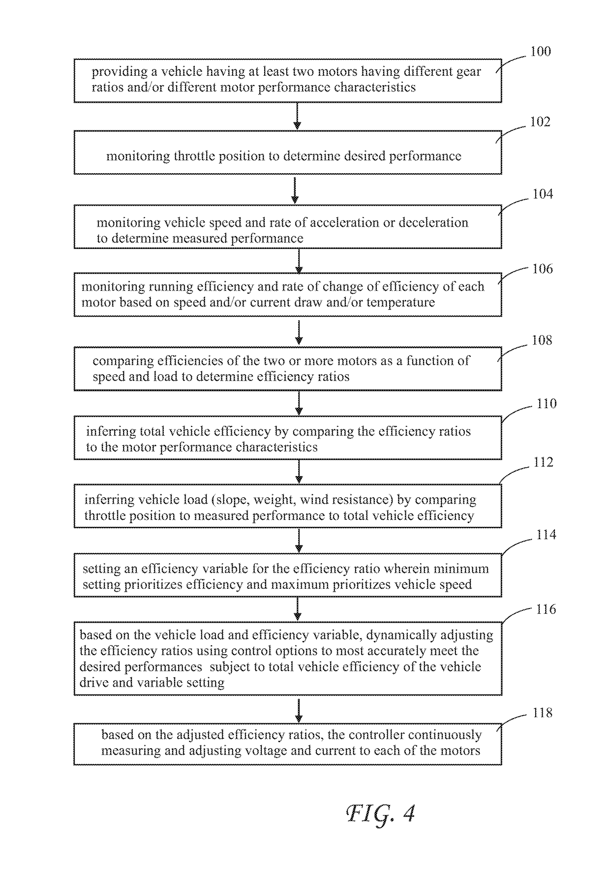
[0027]FIG. 3 shows a front or rear view of a three or four wheeled vehicle 20 having a seat 36, a front wheel 22a, and two motors 24a and 24b independently powering two independent wheels 22b and 22c. The motor 24a drives the wheel 22b through gears 26 and the motor 24b drives the wheel 22c through chain or belt 28. Sprague (or one way) clutches 30 may reside between the motors 24a and 24b and the axles 34a and 34b respectively to decouple a motor not providing torque to the wheels 22b and 22c. The motors 24a and 24b may be controlled as described for FIG. 2 to optimize efficiency.

[0028]A blend of the configurations may be used because the motor style used in the vehicle 20 may often generate low end torque more efficiently. Therefore some embodiments may have a “first gear” which is chain or belt driven and a “second gear” which is hub motor driven.

[0029]Additionally, for heavier applications, each wheel might have its own complete drive. That is, a wheel may be driven by one hub m...


PUM


Abstract

A Light Electric Vehicle (LEV) 10, 20 includes two motors 24a, 24b and independent control of each motor. The two motors have different drive ratios (for example, gearing 26 or pulley / sprocket 28 ratios) or different efficiency versus RPM curves and are controlled to provide efficient operation over a wider speed range than possible with a single motor or two motors having the same efficiency at any given vehicle speed.

Description

CROSS-REFERENCE TO RELATED APPLICATIONS[0001]The present application claims the priority of U.S. Provisional Patent Application Ser. No. 62 / 302,945 filed Mar. 3, 2016, and PCT Application Serial No. PCT / US17 / 20712 filed Mar. 3, 2017, which applications are incorporated in their entirety herein by reference.TECHNICAL FIELD[0002]The present invention relates to electric vehicles and in particular to efficient control of electric vehicle motors.BACKGROUND ART[0003]Known Light Electric Vehicles (LEVs) are two, three or four wheel vehicles which are generally lower in speed and load capability than full size Electric Cars or Trucks. LEVs include electric bikes, scooters, tricycles and small 4 wheel vehicles designed for non-highway use. Given the limited energy density of known batteries, obtaining maximum efficiency from the vehicle's propulsion system is essential with this class of vehicles. Also, given the nature of the market for these vehicles, price sensitivity is extremely high f...

Claims


Application Information

Patent Timeline
Patent Type & Authority Applications(United States)
IPC IPC(8): B62M6/65B62M6/45B60K1/02B60K17/04B60K7/00B60L15/20
CPCB62M6/65B62M6/45B60K1/02B60K17/043B60K7/0007B60L15/2036B60K2007/0046B60K2007/0061B60L2200/12B60L2240/12B60L2240/14B60L2240/421B60L2240/425B60L2240/427B60L2240/429B60L2240/642B60L2240/66B60L2250/26B60Y2200/122B60Y2200/13Y02T90/16Y02T10/72B62M6/60Y02T10/64B60L50/20
Inventor JACKSON, BRITTBOYLE, THOMAS
Owner JACKSON BRITT
Why Eureka
Try Eureka