
Air cleaning apparatus

a technology of air cleaning and air filter, which is applied in the direction of efficient regulation technologies, domestic heating, machines/engines, etc., can solve the problems of increasing air pollution problems in our country, weakening or disappearing static electricity of electrostatic filter screens, and invalid blocking effects of pollutant, so as to improve the air quality of the surrounding environment and poor cleaning performan

Inactive Publication Date: 2019-02-28
MICROJET TECH
View PDF0 Cites 5 Cited by
  • Summary
  • Abstract
  • Description
  • Claims
  • Application Information

AI Technical Summary

Benefits of technology

The present invention is an air cleaning apparatus that solves the problems of poor cleaning performance and being too bulky to carry around. It uses a filter element made of graphene material, which can filter the air effectively, especially for small pollutants. The apparatus is lightweight, portable, and suitable for users to carry around. It also has a miniaturized actuator that can continuously inhale external air, resulting in a stable and consistent internal air flow for improved air detection. Additionally, the apparatus can monitor the air quality of the surrounding environment and automatically perform air purification, ensuring the users' ambient air quality is maintained at any time and anywhere.

Problems solved by technology

Nowadays, the air pollution problems are becoming increasingly serious in our country and its neighboring regions.
However, while the electrostatic filter screen meets the moisture, the static electricity of the electrostatic filter screen may weaken or disappear.
It causes the blocking effect of the pollutant to be invalid.
At the same time, the electrostatic filter has a certain volume, which is not conducive to the design and manufacture of a portable air cleaning apparatus.

Method used


Image

  • Air cleaning apparatus
  • Air cleaning apparatus
  • Air cleaning apparatus

Examples


Embodiment Construction

[0019]The present disclosure will now be described more specifically with reference to the following embodiments. It is to be noted that the following descriptions of preferred embodiments of this disclosure are presented herein for purpose of illustration and description only. It is not intended to be exhaustive or to be limited to the precise form disclosed.

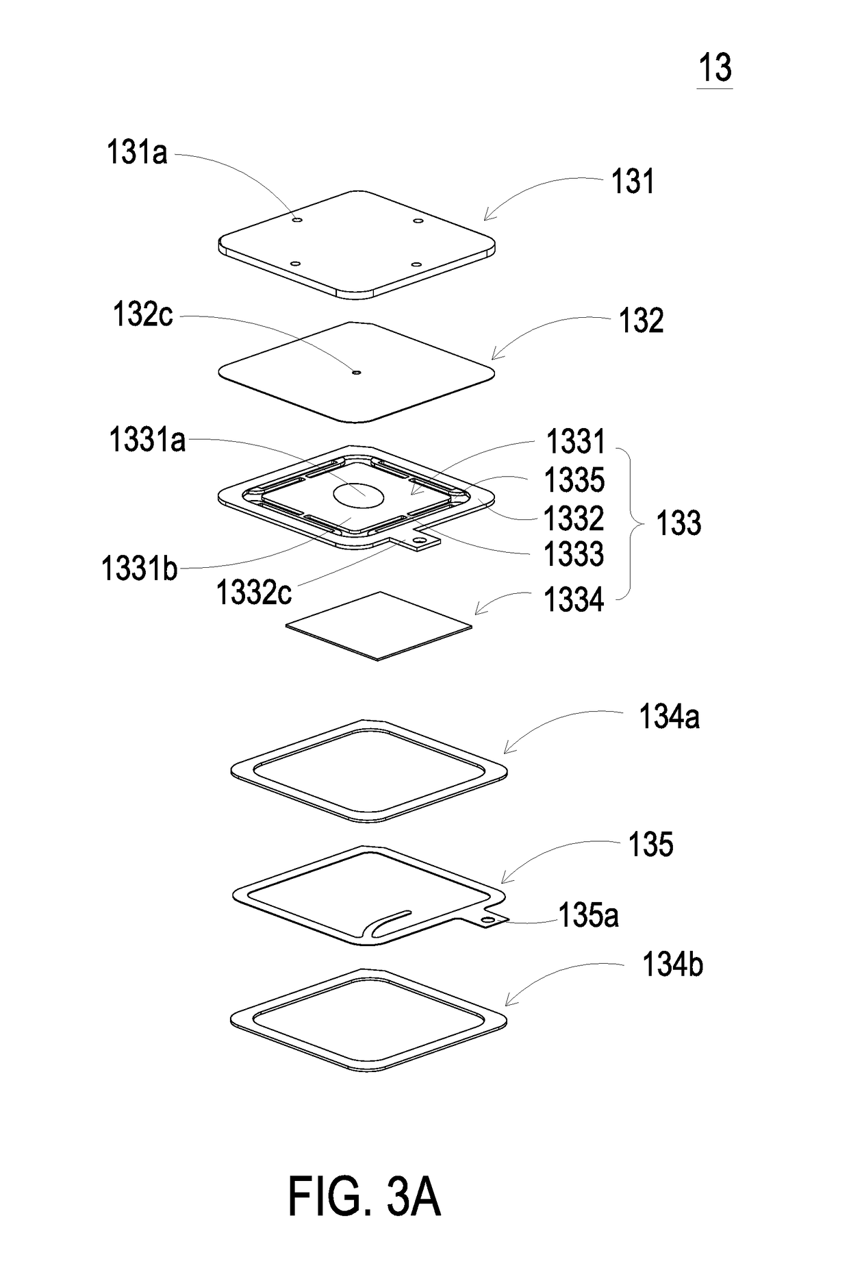
[0020]Please refer to FIGS. 1 and 2. The present disclosure provides an air cleaning apparatus 100 including at least one housing 101, at least one inlet through hole 1011, at least one outlet though hole 1012, at least one air, at least one air cleaning unit 2 and at least one filter element. The number of the housing 101, the inlet through hole 1011, the outlet through hole 1012, the air, the air cleaning unit 2 and the filter element is exemplified by one for each in the following embodiments but not limited thereto. It is noted that each of the housing 101, the inlet through hole 1011, the outlet through hole 1012, the air,...


PUM

PropertyMeasurementUnit
Flow rateaaaaaaaaaa

Abstract

An air cleaning apparatus includes a housing, an actuating and sensing module and an air cleaning unit. The housing includes an inlet through hole and an outlet through hole. The actuating and sensing module and the air cleaning unit are disposed inside the housing. The actuating and sensing module includes an actuator and a sensor. The actuator drives external air to flow into an interior of the housing via the inlet through hole and discharge the air via the outlet through hole, so as to form an internal air flow. The sensor detects at least one detecting target in the internal air flow to generate an air detection result. The air cleaning unit includes a filter element made of a graphene material and disposed adjacent to the actuator, so that the internal air flow is cleaned by the filter element.

Description

FIELD OF THE DISCLOSURE[0001]The present disclosure relates to an air cleaning apparatus, and more particularly to an air cleaning apparatus including a filter element made of a graphene material.BACKGROUND OF THE DISCLOSURE[0002]Nowadays, the air pollution problems are becoming increasingly serious in our country and its neighboring regions. In particular, the concentration of fine suspended particles (PM 2.5) is often too high, and the public gradually starts to pay attention to the cleaning and protection of various airborne pollutants in their daily lives, so as to maintain their health and prevent from the respiratory diseases.[0003]Currently, most of the conventional air cleaning apparatus adsorbs the pollutants in the air by means of the electrostatic principle. However, while the electrostatic filter screen meets the moisture, the static electricity of the electrostatic filter screen may weaken or disappear. It causes the blocking effect of the pollutant to be invalid. At th...

Claims


Application Information

Patent Timeline
IPC IPC(8): B01D53/04G01N33/00F24F8/108F24F8/158F24F8/167
CPCB01D53/0407G01N33/0027B01D53/0454B01D2253/102B01D2257/708F04B45/047F04B49/065F24F2110/74F24F2110/70F24F2110/72F24F2110/76F24F11/77F24F2110/65Y02B30/70F24F8/108F24F8/167F24F8/158F04B53/16F04B39/123F04B39/121F04B39/16
Inventor MOU, HAO-JANHUANG, CHI-FENGHAN, YUNG-LUNGCHEN, HSUAN-KAI
Owner MICROJET TECH
Learn More