Hydraulic control device

a control device and hydraulic technology, applied in the direction of machines/engines, positive displacement liquid engines, servomotors, etc., can solve the problems of pressure pulsation, pressure of the second oil to be supplied to the hydraulic operation unit also pulsation, etc., to prevent the pressure of the second oil and avoid unnecessary workload of the second pump

Active Publication Date: 2019-02-14
HONDA MOTOR CO LTD
View PDF4 Cites 5 Cited by
  • Summary
  • Abstract
  • Description
  • Claims
  • Application Information

AI Technical Summary

Benefits of technology

The patent describes a system for supplying oil to a hydraulic operation unit in a vehicle. The system includes two pumps, one for supplying oil from a tank and another for increasing the pressure of the oil. The system uses a bypass valve to control the flow of oil to the hydraulic operation unit. This allows for a quick and stable pressure of the oil to be obtained, reducing hunting at the bypass valve and pulsation. The system also improves fuel efficiency by reducing power consumption and increasing fuel efficiency while suppressing pulsation.

Problems solved by technology

However, reducing the pressure of the first oil while increasing the rotation number of the second pump may cause the pressure to pulsate.
As a result, there is a possibility that the pressure of the second oil to be supplied to the hydraulic operation unit also pulsates.

Method used


Image

  • Hydraulic control device
  • Hydraulic control device
  • Hydraulic control device

Examples


Embodiment Construction

[0035]A preferred embodiment of a hydraulic control device according to the present invention will hereinafter be described in detail with reference to the attached drawings.

[1. Structure of the Present Embodiment]

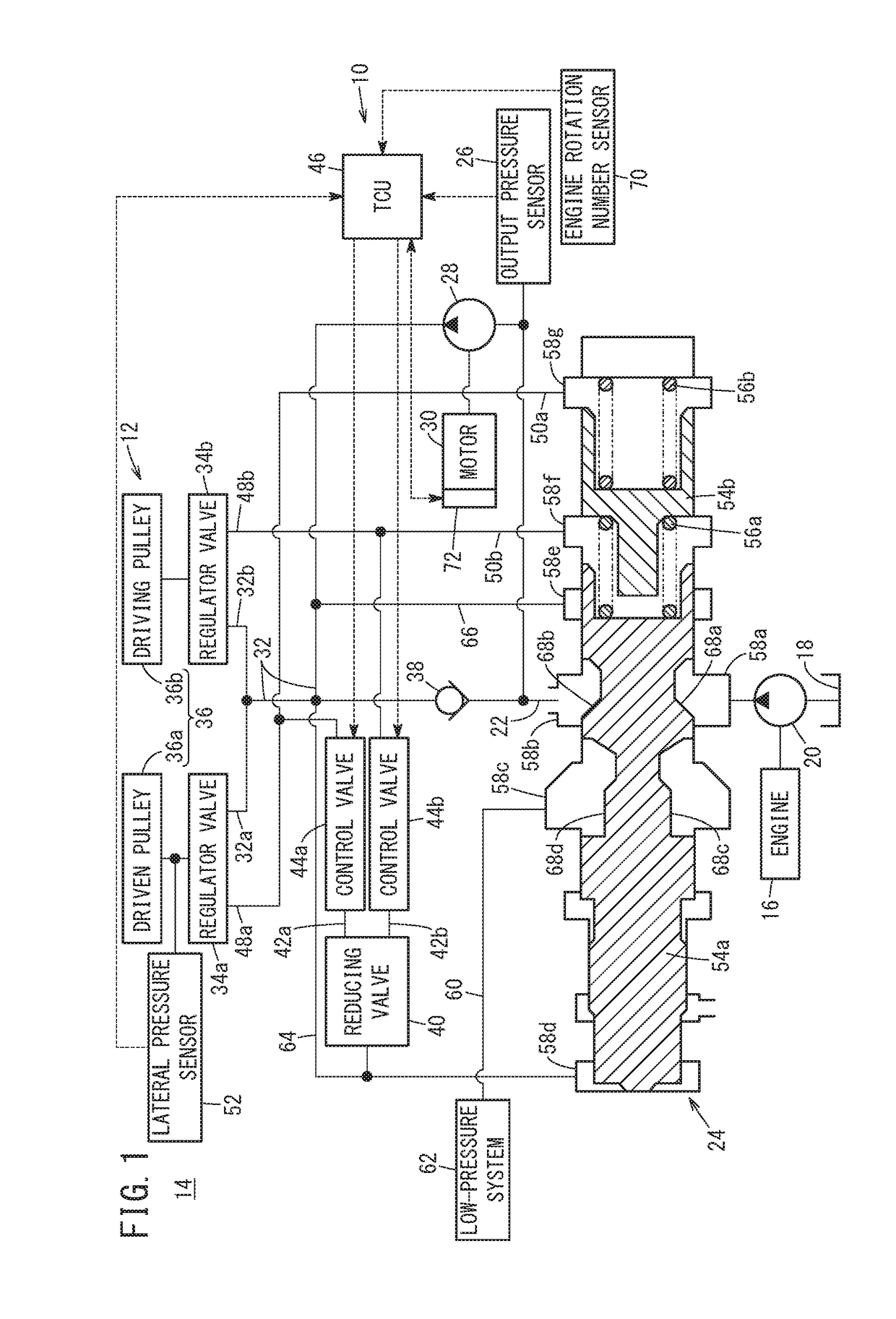
[0036]FIG. 1 is a structure diagram of a hydraulic control device 10 according to the present embodiment. The hydraulic control device 10 is used in, for example, a vehicle 14 including a transmission 12 corresponding to a continuously variable transmission (CVT).

[0037]The hydraulic control device 10 includes a first pump 20 that is a gear pump driven by an engine 16 of the vehicle 14 and pumps up oil (hydraulic oil) stored in a reservoir 18 and transfers the oil with pressure. An output side of the first pump 20 is connected to an oil passage (first flow passage) 22. The oil that is transferred with pressure from the first pump 20 flows as first oil in the oil passage 22. In the middle of the oil passage 22, a line pressure control valve 24 corresponding to a spool valve ...


PUM


Abstract

In a hydraulic control device, when it is detected that a pressure of first oil (output pressure) detected by an output pressure sensor pulsates, a transmission control unit as a TCU stops driving of a second pump or decreases a rotation number of the second pump as a first operation. Alternatively, when it is detected that the output pressure pulsates, the TCU increases the rotation number of the second pump to a rotation number (for example, maximum rotation number) that is higher than a target rotation number as a second operation.

Description

CROSS-REFERENCE TO RELATED APPLICATION[0001]This application is based upon and claims the benefit of priority from Japanese Patent Application No. 2017-155233 filed on Aug. 10, 2017, the contents of which are incorporated herein by reference.BACKGROUND OF THE INVENTIONField of the Invention[0002]The present invention relates to a hydraulic control device that has, between a first pump and a hydraulic operation unit, a second pump and a bypass valve connected in parallel, and that supplies first oil from the first pump to the hydraulic operation unit through the bypass valve, or pressurizes the first oil with the second pump and supplies the first oil that has been pressurized to the hydraulic operation unit as second oil.Description of the Related Art[0003]For example, Japanese Laid-Open Patent Publication No. 2015-200369 discloses a hydraulic control device in a transmission of a vehicle that has, between a first pump that is mechanical and a hydraulic operation unit of the transmi...

Claims


Application Information

Patent Timeline
Patent Type & Authority Applications(United States)
IPC IPC(8): F15B11/17F16H61/00
CPCF15B11/17F16H61/0031F15B2211/20576F15B2211/275F15B2211/6651F15B2211/6306F16H2059/683F16H59/68F16H61/0009F16H61/662F16H61/664F16H61/0267F16H63/50F15B2211/2654F15B2211/8616F15B21/008F04B49/007F04B11/00F04B23/12F04B2205/13F04B49/02F04B49/20F04C14/06F04C14/12F04C11/001F04C15/0049F04C14/08F04C28/02F04C14/26F04C2270/14F04C14/02
Inventor HIRAI, SHINICHI
Owner HONDA MOTOR CO LTD
Why Eureka
Try Eureka