A method, apparatus, and system for data transmission

a data transmission and data technology, applied in the field of communication, can solve the problems of large mtc equipment quantity, large signal expenditure in the network, and poor safety performan

Active Publication Date: 2019-02-07
ZTE CORP
View PDF0 Cites 2 Cited by
  • Summary
  • Abstract
  • Description
  • Claims
  • Application Information

AI Technical Summary

Benefits of technology

[0047]With the implementation of the present embodiments, the network-side network element instructs the terminal to select a data transmission method. By doing so, different data transmission methods can be used for dif

Problems solved by technology

Operations that support MTC devices typically do not have strict requirements with regard to time delays, but could have sensitive materials that require high speed transmission.
The quantity of MTC equipment could be enormous, and large-scale equipment access could bring large-scale signal expenditure to the network.
However, within the control plane optimization mode exist the following deficits: (1) Safety performance can be somewhat poor.
Because no DRB response is established in the control plane optimization program, neither the network-side nor the terminal have the AS security context, and there is no way to implement AS layer encryption on the data.
(2) It is not very suitable for the transmission of relatively large quantities of data, considering that the NAS PDU attached to the signal is very limited.
As a result, the length of the transmitted data packet is limited.
Since MTC equipment typically has poor coverage, packets are easily lost.
As a result, it is difficult for the receiver to receive a complete packet.
Furthermore, control plane optimization utilizes signaling for data transmission; too many small packets will bring too much signal transmission, which will occupy too many resources.
(3) Low-priority data services occupy too many scheduling resources.
This could result in more Air Interface failures.
This could result in being unable to guarantee the high-priority service scheduling of DRB transmission.
However, the user plane optimization mode has the following deficits: (1) The result of sign

Method used


Image

  • A method, apparatus, and system for data transmission
  • A method, apparatus, and system for data transmission
  • A method, apparatus, and system for data transmission

Examples


embodiment 1

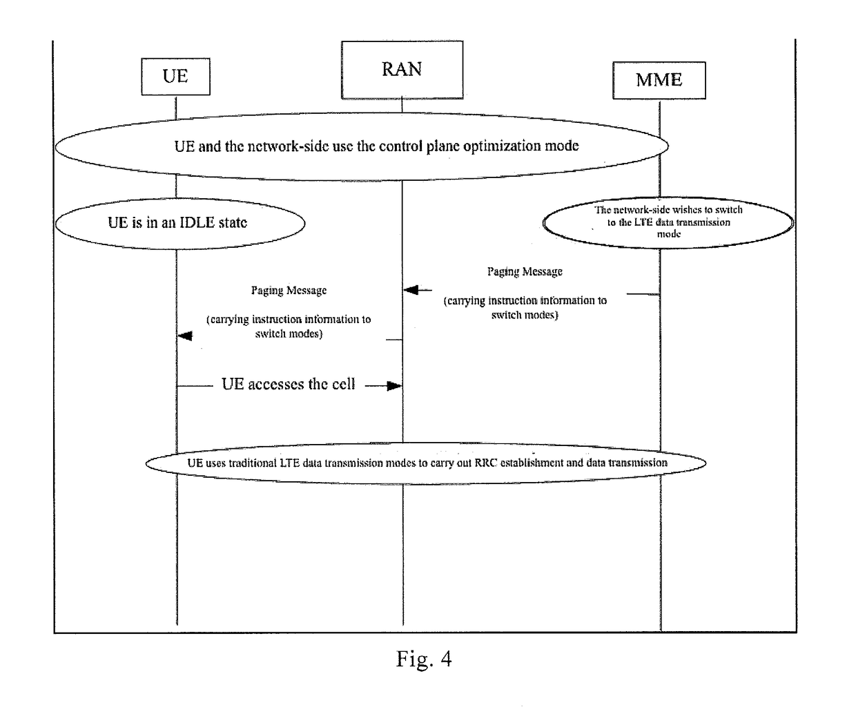
[0094]Within the present embodiment, User Equipment (UE) and the network-side both support the LTE data transmission mode and the control plane optimization mode. The UE and the network-side currently negotiate to use the control plane optimization mode through the ATTACH process, and the UE is currently in an IDLE state; the network-side uses the downlink paging messages carrying instruction information to instruct the UE to switch from the control plane optimization mode to the LTE data transmission mode.

[0095]As FIG. 4 shows, the method provided by the present embodiment comprises: in S101, the network-side has a large amount of data for transmission, such as a software version update, and wishes to switch to the LTE data transmission mode for transmission; MME transmits paging messages on the S1 interface to the RAN node (e.g., the base station), which contain instructions to switch to the LTE data transmission mode; the base station transmits paging messages on the Uu interface...

embodiment 2

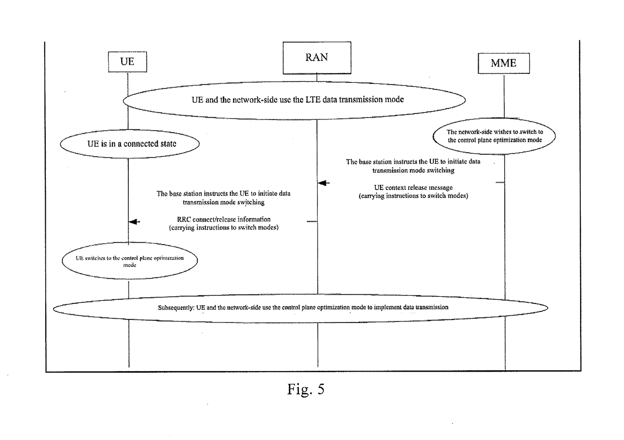
[0096]Within the present embodiment, the UE and the network-side both support the LTE data transmission mode and the control plane optimization mode. The UE and the network-side currently consult to use the control plane optimization mode through the ATTACH process; the UE is currently in a connected state; the network-side switches the control plane optimization mode to the LTE transmission mode by releasing the current RRC connection and then re-accessing.

[0097]The method of the present embodiment comprises: in S201, the network-side has a large amount of data for transmission, such as a software version update, and wishes to switch to the LTE data transmission mode for transmission; MME transmits a UE CONTEXT RELEASE COMMAND message, which contains instructions to switch to the LTE data transmission mode, to the base station; the base station transmits an RRCConnectionRelease message on the Uu interface to the UE, which contains instructions to switch to the LTE data transmission...

embodiment 3

[0098]Within the present embodiment, the UE and the network-side both support the LTE data transmission mode and the control plane optimization mode. The UE and the network currently consult to utilize the control plane optimization mode through the ATTACH process; the UE is currently in a connected state; the network-side switches the control plane optimization mode to the LTE data transmission mode using RRC reconfiguration.

[0099]The method of the present embodiment comprises: in S301, the network-side has a large amount of data for transmission, such as a software version update, and wishes to switch to the LTE data transmission mode for transmission; MME transmits an INITIAL CONTEXT

[0100]SETUP REQUEST message to the base station, which contains instructions to switch to the LTE data transmission mode, Radio Access Bearer (RAB) information requiring establishment, and AS context, etc.; in S302, the base station creates the RAB bearer information and the air interface Radio Bearer...


PUM


Abstract

A method, apparatus, and system for data transmission, wherein the method comprises: the network-side network element determining the target data transmission mode; the network-side network element sending instruction information to the terminal through the base station transmission in order to instruct the terminal to switch to the target data transmission mode with which to implement data transmission; wherein, the target data transmission mode is NarrowBand IoT (NB-IoT) data transmission or Long-Term Evolution (LTE) data transmission.

Description

FIELD OF THE INVENTION[0001]The present disclosure is related to the field of Communications, especially a method, apparatus, and system for data transmission.BACKGROUND[0002]Following the swift development of wireless communication technology and the increasing demand for communications, the fifth generation of communication technology (5G) is fast approaching. An important application of 5G is Machine-Type Communications (MTC), which, with their large-scale potential for application, have garnered attention from a large number of mobile network operators, equipment manufacturers, and research institutes. MTC applications such as Smart Grid, Intelligent Transportation, Smart Home (Home Automation), remote monitoring, and wireless censoring networks make up an important part of the burgeoning Internet of Things (IoT).[0003]Services that support MTC devices are varied. Requirements for most MTC equipment usually include low cost and low power usage, such as the equipment used for env...

Claims


Application Information

Patent Timeline
IPC IPC(8): H04W4/70H04L12/24
CPCH04W4/70H04L41/0803H04W28/0215H04W28/24H04W76/12H04W76/27H04W76/32H04L41/0823
Inventor HUANG, MEIQINGDAI, QIANYU, YUANFANGGAO, YIN
Owner ZTE CORP
Why Eureka
Try Eureka