
High performance electrodes, materials, and precursors thereof

Active Publication Date: 2019-02-07
CORNELL UNIVERSITY
View PDF0 Cites 2 Cited by
  • Summary
  • Abstract
  • Description
  • Claims
  • Application Information

AI Technical Summary

Benefits of technology

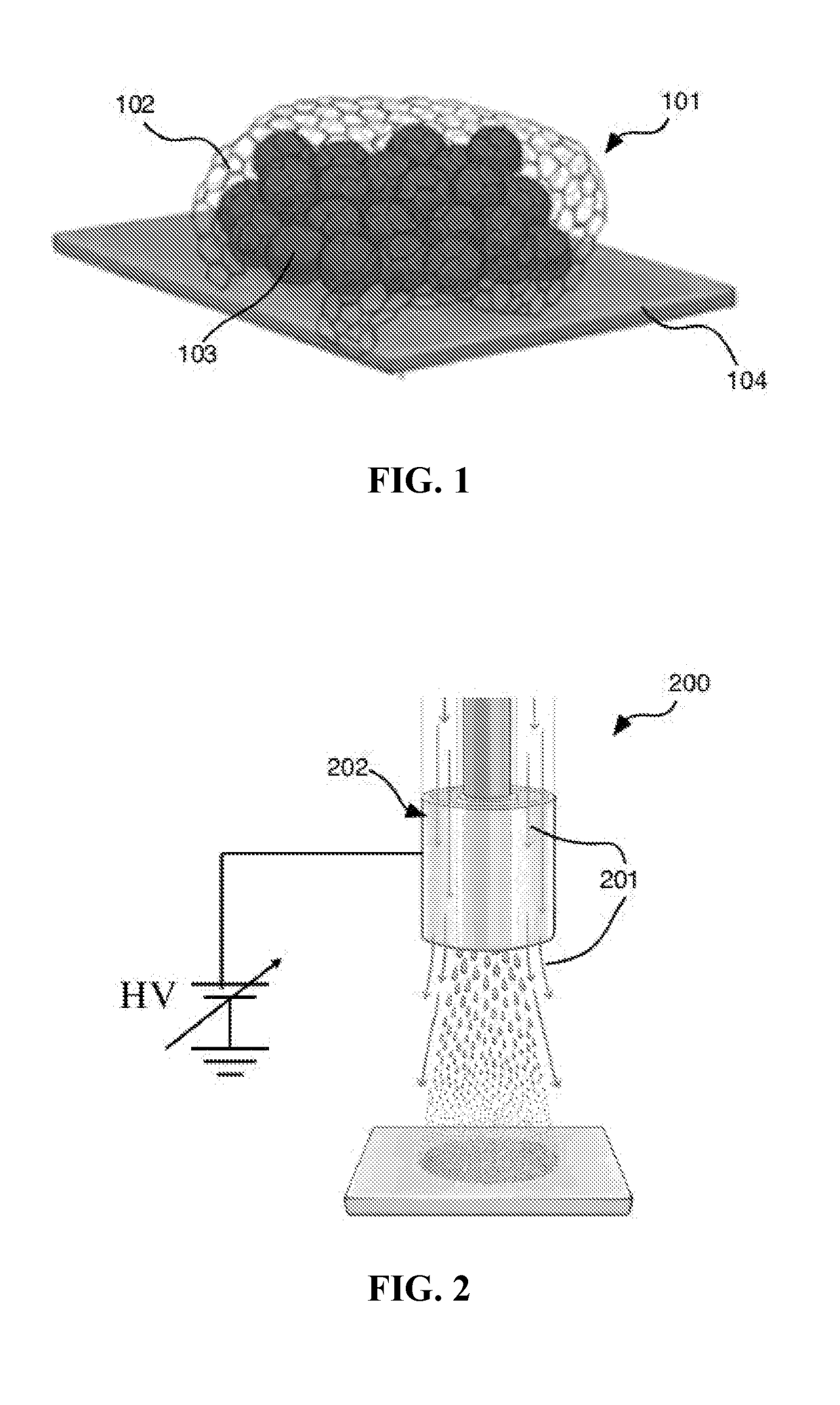
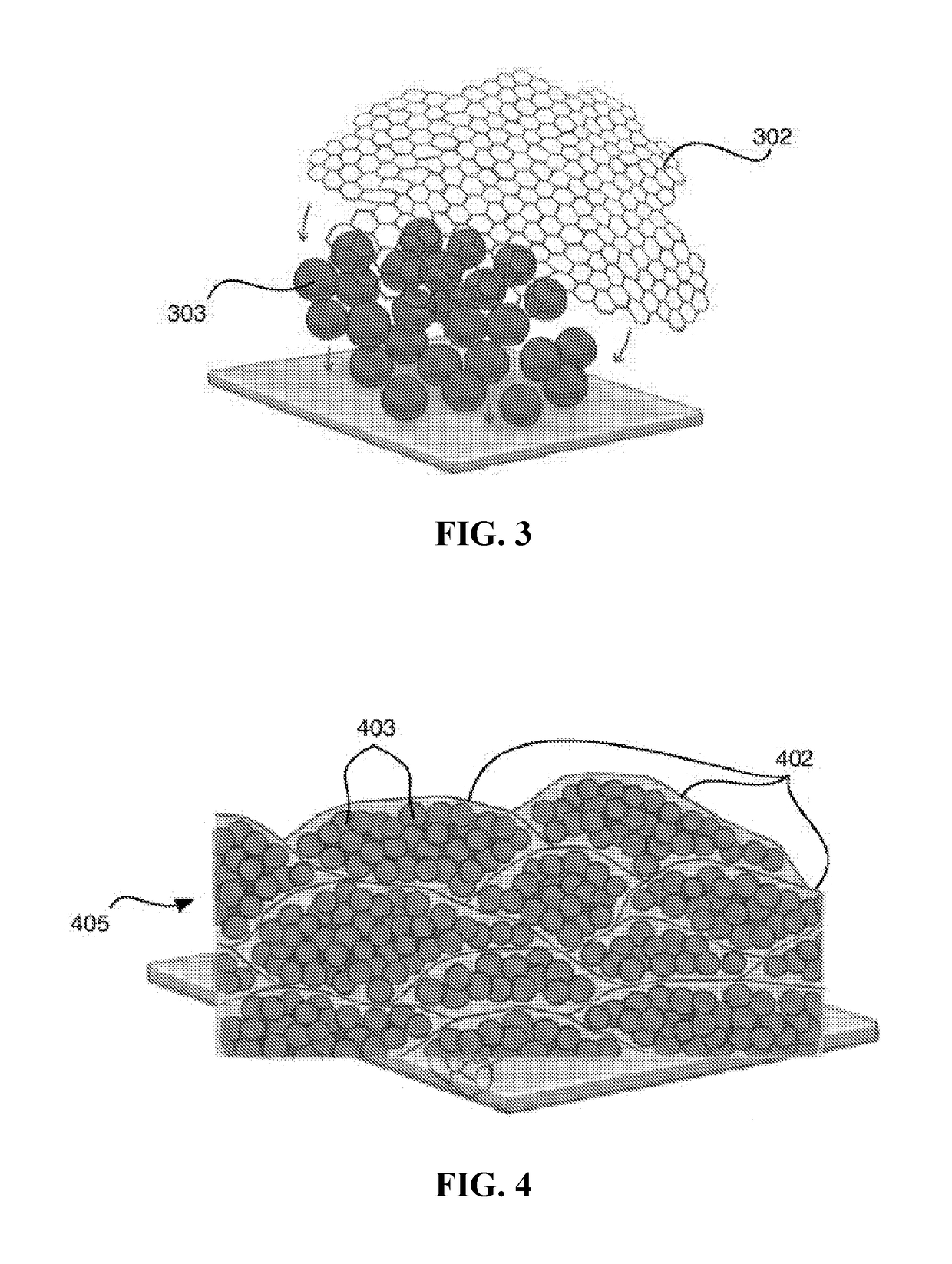
The patent describes a process for making electrode materials by generating a plume or aerosol from a fluid stock containing a conductive inclusion and an active electrode material. The plume is generated using a high velocity gas, which helps to fine disperse the plume particles. The plume is then collected on a substrate surface. The process can control the deposition of the inclusions, resulting in a well-dispersed and well-controlled multi-component system. The plume particles have a low concentration of inclusions, reducing the likelihood of damage to the active electrode material during deposition. The process also allows for the expansion of the active electrode material during lithiation without displacing the web coating or reducing the overall volume expansion of the electrode material.

Problems solved by technology

Alternate approaches to achieving higher performance materials and electrodes have had extremely limited and incremental success, with some attempts resulting in catastrophic failure, and / or development of un-scalable, and non-commercializable products and processes.
In particular, silicon containing electrode materials suffer from poor performance characteristics, such as poor capacity retention on cycling, such as due to the formation of solid electrolyte interface (SEI) layers, pulverization, and the like.

Method used


Image

  • High performance electrodes, materials, and precursors thereof
  • High performance electrodes, materials, and precursors thereof
  • High performance electrodes, materials, and precursors thereof

Examples


example 1

[0154]A fluid stock is prepared by combining silicon nanoparticles, graphene oxide, and water, at a weight ratio of Si NP (7.5%):GO (2.5%):water (90%). The fluid stock is then electrosprayed by injecting the fluid stock into a gas stream, such as using a gas-controlled electrospray nozzle described herein, in the direction of a substrate (e.g., a metal current collector) at a flowrate of 0.2 mL / min under 2 kV / cm. A deposition (electrode) with a mass loading of about 1 to 2 mg / cm2 is collected on the substrate, without the need for adding a binder, or the need for further processing.

[0155]Other electrode / current collector systems are also prepared using silicon nanoparticles and graphene oxide, by blending with Super P (Timcal) and poly(acrylic acid) (PAA, MW=3,000,000) in a weight ratio of 80 (active material):10 (super P):10 PAA in N-methyl-2-pyrrolidinone (NMP) in order to make a slurry. In one example, the slurry is drop cast onto a current collector; in another example, the slur...

example 2

[0159]Full cells are prepared using a mixed lithium colbalt oxide (LCO) cathode and the anode of Example 1. FIG. 9 illustrates full cell data therefor at a charge / discharge rate of 0.1 C. As is illustrated, initial specific capacity of the anode is about 1600 mAh / g, with good cycling retention.

example 3

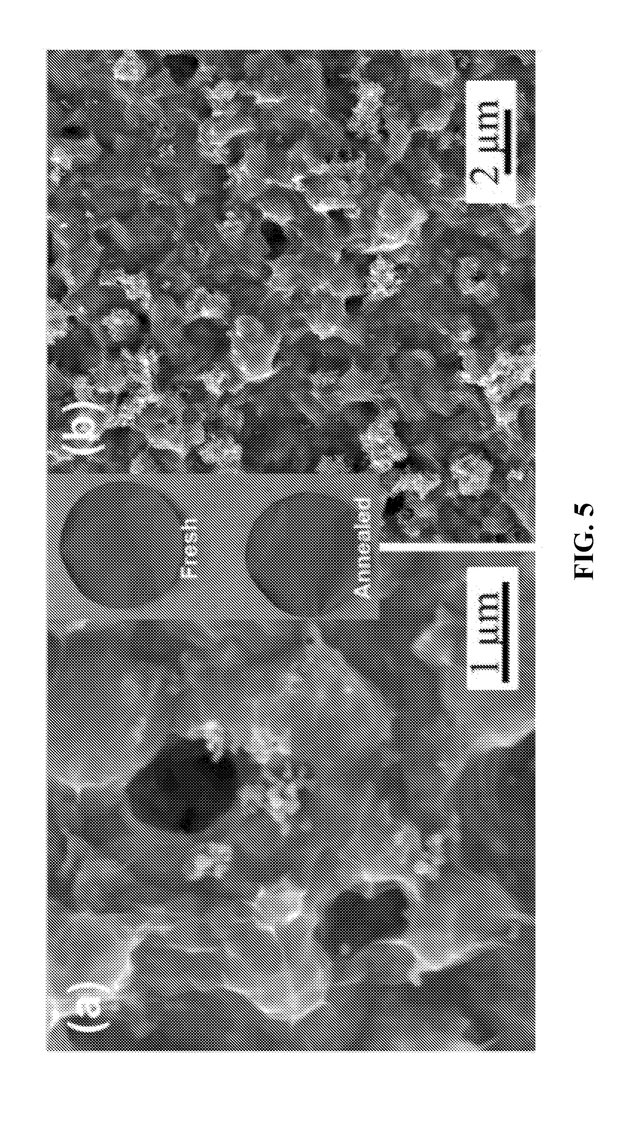
[0160]Electrodes are prepared according to the electrospray techniques described in Example 1. The electrodes are then thermally treated at a temperature of about 200° C. (e.g., to at least partially reduce and / or remove defects of the graphene oxide thereof, thereby converting the graphene oxide to what is referred to herein as reduced graphene oxide). FIG. 5 shows images of the electrosprayed electrode at various magnifications, as well as images of non-thermally treated electrode and thermally treated electrode. FIG. 10 illustrates Coulombic efficiency of various loadings for both thermally treated and non-thermally treated electrodes. As is illustrated, for both loadings, the thermally treated samples (referred to in the figure as “RGO”) demonstrate improved Coulombic efficiency, especially at the first cycle, relative to the non-thermally treated analogs. FIG. 12 illustrates a CV curve for both thermally and non-thermally treated electrodes.


PUM


Abstract

Provided herein are high performance electrodes, electrode materials comprising a plurality of active electrode material-containing particles secured within one or more graphenic web, and precursors thereof. Also provided herein are processes of generating the same by an electrospray process.

Description

CROSS-REFERENCE[0001]This patent application claims the benefit of U.S. Provisional Patent Application Nos. 62 / 254,418, filed Nov. 12, 2015; and U.S. Provisional Patent Application Nos. 62 / 312,871, filed Mar. 24, 2016; and U.S. Provisional Patent Application No. 62 / 354,366, filed Jun. 24, 2016; each of which is incorporated herein by reference in their entirety.FIELD OF THE INVENTION[0002]The field relates to electrodes, particularly negative electrodes in lithium ion batteries, cells and batteries comprising the same, and the manufacturing thereof.BACKGROUND OF THE INVENTION[0003]Batteries comprise one or more electrochemical cell, such cells generally comprising a cathode, an anode and an electrolyte. Lithium ion batteries are high energy density batteries that are fairly commonly used in consumer electronics and electric vehicles. In lithium ion batteries, lithium ions generally move from the negative electrode to the positive electrode during discharge and vice versa when chargi...

Claims


Application Information

Patent Timeline
IPC IPC(8): H01M4/587H01M10/0525H01M4/62H01M4/48H01M4/38H01M4/36
CPCH01M2004/027H01M4/386H01M4/366H01M4/623H01M4/587H01M10/0525H01M4/483H01M4/139H01M4/0419H01M4/13H01M4/485B05B5/03
Inventor JOO, YONG LAKFEI, LING
Owner CORNELL UNIVERSITY
Learn More